What Is a Free Body Diagram?
Free Body Diagrams (FBD) are useful aids for representing the relative magnitude and direction of all forces acting upon an object in a given situation. The first step in analysing and describing most physical phenomena involves the careful drawing of a free body diagram. In a free-body diagram, the size of the arrow denotes the magnitude of the force, while the direction of the arrow denotes the direction in which the force acts.
A free body diagram is defined as follows:
A free body diagram is a graphic, dematerialised, symbolic representation of the body (structure, element or segment of an element) in which all connecting “pieces” have been removed.
Features of a Free Body Diagram
A free body diagram is a diagram that is modified as the problem is solved. Typically, a free body diagram consists of the following components:
- A simplified version of the body (most commonly a box)
- A coordinate system
- Forces are represented as arrows pointing in the direction they act on the body
- Moments showed as curved arrows pointing in the direction they act on the body
The number of forces acting on a body depends on the specific problem and the assumptions made. Commonly, air resistance and friction are neglected.
Exclusions in a Free Body Diagram
Some of the things that a free body diagram excludes are as follows:
- Bodies other than the free body diagram
- Constraints
- Internal forces
- Velocity and acceleration vectors
What Is the Purpose of a Free Body Diagram?
Free body diagrams are tools that are used to visualise the force and moments applied to a body and to calculate the resulting reactions in many types of mechanics problems.
How to Make a Free Body Diagram?
In this section, we will explain the step-by-step procedure of drawing a free body diagram:
1. Identify the Contact Forces
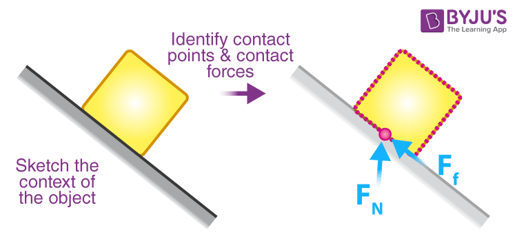
To identify the forces acting on the body, draw an outline of the object with dotted lines, as shown in the figure. Make sure to draw a dot when something touches the object. When there is a dot, it indicates that there is at least one contact force acting on the body. Draw the force vectors at the contact points to represent how they push or pull on the object.

2. After identifying the contact forces, draw a dot to represent the object that we are interested in. Here, we are only interested in determining the forces acting on our object.
3. Draw a coordinate system and label positive directions.
4. Draw the contact forces on the dot with an arrow pointing away from the dot. The arrow lengths should be relatively proportional to each other. Label all forces.
5. Draw and label the long-range forces. This will usually be weight unless there is an electric charge or magnetism involved.
6. If there is acceleration in the system, then draw and label the acceleration vector.
| Common Mistakes Made While Drawing a Free Body Diagram |
The direction of different forces:
|
Free Body Diagram Examples
In this section, we have listed free diagrams considered under different scenarios.
1. A bottle is resting on a tabletop. Draw the forces acting on the bottle.

2. An egg is free-falling from a nest in a tree, neglecting the air resistance. What would the free body diagram look like?

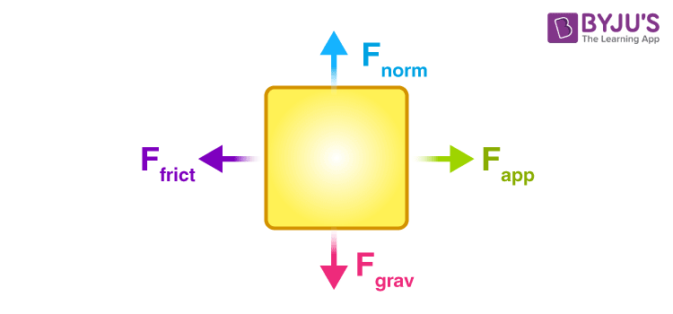
3. If a rightward force is applied to a book in order to move it across a desk at a constant velocity, considering only the frictional forces and neglecting air resistance, a free body diagram for this situation will look like the following:
4. A skydiver is descending at a constant velocity. Considering the air resistance, the free body diagram for this situation will be like the following:
Free Body Diagram Solved Problem
Example: Draw a free body diagram of three blocks placed one over the other, as shown in the figure.

Solution:
The forces acting on the individual elements of the system are shown below:
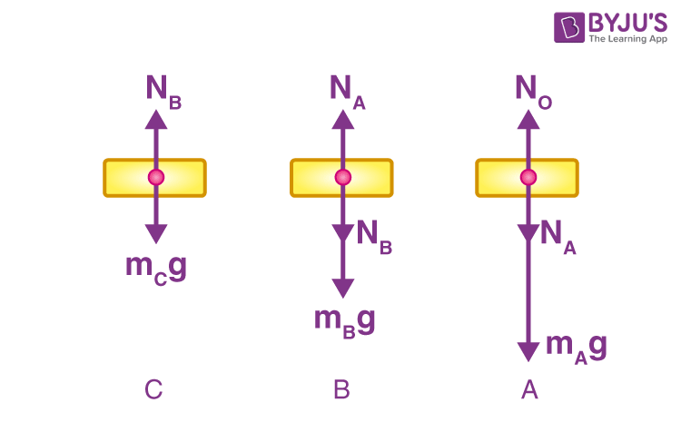
Description of forces acting on each block:
The forces on block “C” are:
WC = mCg = its weight, acting downward
NB = normal reaction on “C” due to the upper surface of block B, acting upward
The forces on block “B” are:
WB = mBg = its weight, acting downward
NB = normal reaction on “B” due to the lower surface of block C, acting downward
NA= normal reaction on “B” due to the upper surface of block A, acting upward
The forces on the block “A” are:
WA = mAg = its weight, acting downward
NA = normal reaction on “A” due to the lower surface of block B, acting downward
NO = normal reaction on “A” due to the horizontal surface, acting upward
The FBD of the blocks as points with external forces are shown below.
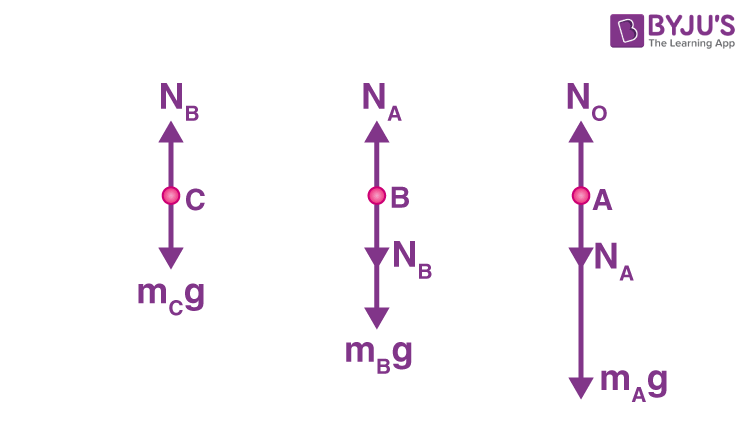
Free Body Diagram

Frequently Asked Questions on Free Body Diagram
What is the definition of a free body diagram?
A free-body diagram is a graphic, dematerialised, symbolic representation of the body (structure, element or segment of an element) in which all connecting “pieces” have been removed.
What does a free body diagram represent?
Free-body diagrams represent the relative magnitude and direction of all forces acting upon an object in a given situation.
How to draw a free body diagram?
While drawing a free body diagram, we draw the object of interest by drawing all the forces acting on it and resolving all force vectors into x– and y-components. Separate free body diagrams should be drawn for each object in the problem.
What is a free body diagram used for?
Free body diagrams are used to visualise the forces and moments applied to a body and to calculate the resulting reactions in many types of mechanics problems.
Comments