Electromagnetic Induction Maxwell’s Equations is an important chapter in Physics that mainly deals with electromagnetic induction. The chapter comprises various numerical based on the syllabus and also the practical applications. I.E. Irodov Physics provides the solution to different varieties of questions where the applications of magnetic field in day-to-day activities is explained. Electromagnetic Induction Maxwell’s Equations is a very vital equation for solving and scoring good marks in any entrance examinations. It is one of the best ways to study and practice for physics examinations to score high. The problems asked here are mainly based on the electric field and magnetic field.
This chapter mainly focuses on formulas and equations based on the magnetic field and electromagnetic induction applications. The numericals are mainly based on the popular Maxwell’s equations that help to determine the electromagnetic phenomenon. The equations have their own importance in practical applications. It helps the students to analyse which law can be applied to solve the problems. The problems given here focus on the variation of magnetic field, how it is applied and its changes with the respective materials. Solving I.E. Irodov Chapter 3.6 Electromagnetic Induction Maxwell’s Equations problems builds the confidence of students and enables them to have a grip over the subject.
1. A wire bent as a parabola y = ax2 is located in a uniform magnetic field of induction B, the vector B being perpendicular to the plane x, y. At the moment t = 0, a connector starts sliding translation wise from the parabola apex with a constant acceleration w (Figure). Find the emf of electromagnetic induction in the loop thus formed as a function of y.

From Lenz’s law, the induced current and hence the e.m.f. in the loop is anticlockwise.
*
From Faraday’s law of electromagnetic induction

2. A rectangular loop with a sliding connector of length l is located in a uniform magnetic field perpendicular to the loop plane (Figure). The magnetic induction is equal to B. The connector has an electric resistance R, the sides AB and CD have resistances R1 and R2 respectively. Neglecting the self-inductance of the loop, find the current flowing in the connector during its motion with a constant velocity v.

Let us assume


As R1 and R2 are in parallel connections.
Question 3. A metal disc of radius a = 25 cm rotates with a constant angular velocity ω = 130 rad/s about its axis. Find the potential difference between the centre and the rim of the disc if
(a) the external magnetic field is absent;
(b) the external uniform magnetic field of induction B = 5.0 mT is directed perpendicular to the disc.
(a) As the metal disc rotates, any free electron also rotates with it with the same angular velocity ω, and that’s why an electron must have an acceleration ω2r directed towards the disc’s centre, where r is the separation of the electron from the centre of the disc. We know from Newton’s second law that if a particle has some acceleration then there must be a net effective force on it in the direction of acceleration.
We also know that a charged particle can be influenced by two fields electric and magnetic. In our problem magnetic field is absent hence we reach the conclusion that there is an electric field near any electron and is directed opposite to the acceleration of the electron.
If E is the electric field strength at a distance r from the centre of the disc, we have from Newton’s second law.
Fn=mwn
eE=mrw2 or
And the potential difference

(b) When field
Hence the sought potential difference,

4. A thin wire AC shaped as a semi a constant angular velocity ω = 100 rad/s in a uniform magnetic circle of diameter d = 20 cm rotates with magntic field of induction B = 5.0 mT, with w ↑↑B. The rotation axis passes through the end A of the wire and is perpendicular to the diameter AC. Find the value of a line integral ∫E dr along the wire from point A to point C. Generalize the obtained result.
By definition
So
But, v = ωr, where r is the perpendicular distance of the point from A.
This result can be generalized to a wire AC of arbitrary planar shape. We have


d being AC and
5. A wire loop enclosing a semi along circle of radius a is located on the boundary of a uniform magnetic field of induction B (Figure). At the moment t = 0 the loop is set into rotation with a constant angular acceleration p about an axis 0 coinciding with a line of vector B on the boundary. Find the emf induced in the loop as a function of time t. The arrow in the figure shows the emf direction taken to be positive.
Flux at any moment of time,

Where φ is the sector angle, enclosed by the field.
Now, magnitude of induced e.m.f. is given by
Where ω is the angular v elocity o f the disc. But as it starts rotating from rest at t = with an angular acceleration p its angular velocity ω (f) = βt. So
According to Lenz law the first half cycle current in the loop is in anticlockwise sense, and in subsequent half cycle it is in clockwise sense
Thus in general,
6. A long straight wire carrying a current I and a II sliding connector are located in the same plane as the shaped conductor shown in Figure. The connector of length l and resistance R slides to the right with a constant velocity v. Find the current induced in the loop as a function of separation r between the connector and the straight wire. The resistance of the H shaped conductor and the self-inductance loop are assumed to be negligible.

Field, due to the current carrying wire in the region, right to it, is directed into the plane of the paper and its magnitude is given by,
Where r is the perpendicular distance from the wire.
As B is same along the length of the rod thus motional e.m.f
And it is directed in the sense of
So, current (induced) in the loop
7. A square frame with side a and a long straight wire carrying a current I are located in the same plane as shown in the figure. The frame translates to the right with a constant velocity v. Find the emf induced in the frame as a function of distance x.

Field, due to the current carrying wire, at a perpendicular distance x from it is given by,
Motional e.m.f is given by
There will be no induced e.m.f. in as, the segments (2) and (4)

Respectively , and their sense will be in the direction of

8. A metal rod of mass m can rotate about a horizontal axis O, sliding along a circular conductor of radius a (figure). The arrangement is located in a uniform magnetic field of induction B directed perpendicular to the ring plane. The axis and the ring are connected to an emf source to form a circuit of resistance R. Neglecting the friction, circuit inductance, and ring resistance, find the law according to which the source emf must vary to make the rod rotate with a constant angular velocity ω.

As the rod rotates, an emf

A magnetic force will then act on the conductor of magnitude BI per unit length. Its direction will be normal to B and the rod and its torque will be
Obviously both magnetic and mechanical torque acting on the C M of the rod must be equal but opposite in sense. Then

9. A copper connector of mass m slides down two smooth copper bars, set at an angle a to the horizontal, due to gravity (Fig. 3.84). At the top the bars are interconnected through a resistance R. The separation between the bars is equal to l. The system is located in a uniform magnetic field of induction B, perpendicular to the plane in which the connector slides. The resistances of the bars, the connector and the sliding contacts, as well as the self assumed to be negligible. Find the steady inductance of the loop, are state velocity of the connector.

From Lenz’s law the current through the connector is directed form A to B. Here
where v is the velocity of the rod at any moment.

For the rod, from Fx=mwx
For steady state, acceleration of the rod must be equal to zero
Hence,
But,
From (1) and (2)
10. The system differs from the one examined in the foregoing problem (Figure) by a capacitor of capacitance C replacing the resistance R. Find the acceleration of the connector.

From Lenz’s 1 aw, the current to 2 or in other words, the induced through the copper bar is directed from 1 current in the circuit is in clockwise sense.

Potential difference across the capacitor plates
Hence, the induced current in the loop
But the variation of magnetic flux through the loop is caused by the movement of the bar. So, the induced e.m.f

11. A wire shaped as a semicircle of radius a rotates about an axis OO’ with an angular velocity ω in a uniform magnetic field of induction B (Figure). The rotation axis is perpendicular to the field direction. The total resistance of the circuit is equal to R. Neglecting the magnetic field of the induced current, find the mean amount of thermal power being generated in the loop during a rotation period.

Flux
From Faraday’s law, induced e.m.f

12. A small coil is introduced between the poles of an electromagnet so that its axis coincides with the magnetic field direction. The cross-sectional area of the coil is equal to S = 3.0 mm2 the number of turns is N = 60. When the coil turns through 180° about its diameter, a ballistic galvanometer connected to the coil indicates a charge q = 4.5 μC flowing through it. Find the magnetic induction magnitude between the poles provided the total resistance of the electric circuit equals R = 40Ω.
The flux through the coil changes sign. Initially, it is BS per turn. Finally, it is -Bs per turn. Now if flux is

13. A square wireframe with side a and a straight conductor carrying a constant current I are located in the same plane (Figure). The inductance and the resistance of the frame are equal to L and R respectively. The frame was turned through 180° about the axis OO’ separated from the current carrying conductor by a distance b. Find the electric charge having flown through the frame.

According to Ohm’s law and Faraday’s law of induction, the current i0 appearing in the frame, during its rotation, is determined by the formula
Hence, the required amount of electricity (charge) is,
Since the frame has been stopped after rotation, the current in it vanishes, and hence Δ i0 = 0. It remains for us to find the increment of the flux

Let us choose the normal
14. A long straight wire carries a current Io. At distances a and b from it there are two other wires, parallel to the former one, which are interconnected by a resistance R (Figure). A connector slides without friction along the wires with a constant velocity v. Assuming the resistances of the wires, the connector, the sliding contacts, and the self-inductance of the frame to be negligible, find:
(a) the magnitude and the direction of the current induced in the connector;
(b) the force required to maintain the connector’s velocity constant.
As

(a) The flux of changes through the loop due to the movement of the connector. According to Lenz’s law, the current in the loop will be anticlockwise. The magnitude of motional e.m.f.
(b)The force required to maintain the constant velocity of the connector must be the magnitude equal to that of Ampere’s acting on the connector, but in opposite direction.
15. A conducting rod AB of mass m slides without friction over two long conducting rails separated by a distance l (Figure). At the left end, the rails are interconnected by a resistance R. The system is located in a uniform magnetic field perpendicular to the plane of the loop. At the moment t = 0 the rod AB starts moving to the right with an initial velocity vo. Neglecting the resistance of the rails and the rod AB, as well as the self-inductance, find:
(a) the distance covered by the rod until it comes to a standstill;
(b) the amount of heat generated in the resistance R during this process.
The flux through the loop changes due to the movement of the rod AB. Recording to Lenz’s law current should be anticlockwise in the sense as we have assumed
And, induced current

From Newton’s law in projection form fx=mwx
(b)From equation of energy conservation; Ef,-Ei+ Heat liberated= Acell+ Aext
So heat liberated =
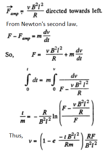
16. A connector AB can slide without friction along a Shaped cell + A ext conductor located in a horizontal plane (Figure). The connector has a length l, mass m, and resistance R. The whole system is located in a uniform magnetic field of induction B directed vertically. At the moment t = 0 a constant horizontal force F starts acting on the connector shifting it translation wise to the right. Find how the velocity of the connector varies with time t. The inductance of the loop and the resistance of the II shaped conductor are assumed to be negligible.

With the help of the calculation, done in the previous problem, Ampere’s force on the connector,

From Newton’ second law
17. Figure illustrates plane figures made of thin conductors which are located in a uniform magnetic field directed away from a reader beyond the plane of the drawing. The magnetic induction starts diminishing. Find how the currents induced in these loops are directed.

According to Lenz, the sense of induced e.m.f. is such that it opposes the cause of change of flux. In our problem, the magnetic field is directed away from the reader and is diminishing.

So, in figure (a), in the round conductor, it is clockwise and there is no current in the connector
In figure (b) in the outside conductor, clockwise.
In figure (c) in both the conductor, clockwise; and there is no current in the connector to obey the charge conservation.
In figure (d) in the left side of the figure, clockwise
18. A plane loop shown in figure is shaped as two squares with sides a = 20 cm and b = 10 cm and is introduced into a uniform magnetic field at right angles to the loop’s plane. The magnetic induction varies with time as B = B where B0sin ωt the loop if its resistance Bo= 10 mT and ω = 100s-1 . Find the amplitude, of the current induced in per unit length is equal to p = 50 mΩ/m. The inductance of the loop is to be neglected.
The loops are connected in such a way that if the current is clockwise in one, it is anticlockwise in the other. Hence the e.m.f. in loop b opposes the e.m.f. in loop
a. EMF in the loop
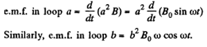
Hence, net e.m.f. in the circuit
as both the e.m.f’s are in opposite sense, and resistance of the circuit = 4 (a + b) p
Hence amplitude of current =
19. A plane spiral with a great number N of turns wound tightly to one another is located in a uniform magnetic field perpendicular to the spiral’s plane. The outside radius of the spiral’s turns is equal to a. The magnetic induction varies with time as B = B0 sin ωt, where B0 and ω are constants. Find the amplitude of emf induced in the spiral.
The flat shape is made up of concentric loops, having different radii, varying from 0 to a. Let us consider an elementary loop of radius r, then e.m.f. induced due to this
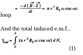
Where π r2 ω cos ωt is the contribution of one turn of radius r and dN is the number of turns in the interval [r, r + dr].
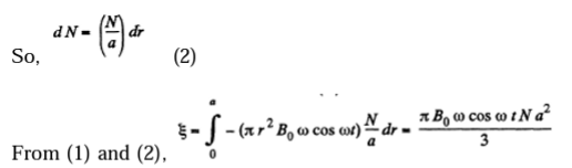
Maximum value of e.m.f. Amplitude
20. An H-shaped conductor is located in a uniform magnetic field perpendicular to the plane of the conductor and varying with time at the rate B=0.10T/s. A conducting connector starts moving with an acceleration w = 10 cm/s2 along the parallel bars of the conductor. The length of the connector is equal to l = 20 cm. Find the emf induced in the loop t = 2.0 s after the beginning of the motion, if at the moment t = 0 the loop area and the magnetic induction are equal to zero. The inductance of the loop is to be neglected.
The flux through the loop changes due to the variation in
So
But, B, after t sec. of beginning of motion – Bt, and S becomes
as connector starts moving from rest with a constant acceleration w.
Comments