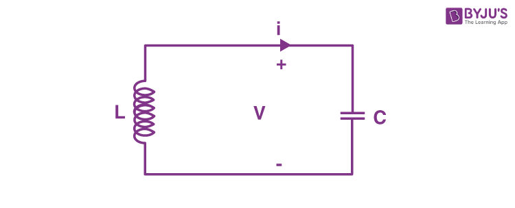
An LC circuit is a type of electric circuit that is made up of an inductor which is expressed by the letter L, and a capacitor, represented by the letter C. Here, both are connected in a single circuit. An LC circuit is also referred to as a tank circuit, resonant circuit, or tuned circuit. LC circuits act as major components in various electronic devices like radio equipment in circuits like filters, oscillators, and tuners.
An LC circuit is a suitable model in many cases mainly because, by using this type of circuit, we can assume that there is no dissipation of energy even if there is any resistance. However, if we have to be practical, any implementation will involve loss because of the small electrical resistance in the connecting wires or components. This type of circuit is used because it can oscillate with minimum damping, making the resistance as low as possible. Nonetheless, most of the circuits work with some loss.
When an LC circuit oscillates at its natural resonant frequency, it can reserve electrical energy. The capacitor, depending on the voltage it receives, will store energy in the electric field (E) between its plates, whereas an inductor depending on the current, will accumulate energy in its magnetic field (B).
Nomenclature
The di elemental LC circuit that we talked about in the above paragraphs is a basic example of an inductor-capacitor network. Moreover, it is also called a second-order LC circuit to differentiate it from highly complicated LC networks that have more capacitors and inductors. These LC networks that consist of more than two reactances can comprise several resonant frequencies.
A resonant frequency is defined as an undamped or natural frequency of a system. In the case of LC circuits, the resonant frequency is usually determined by the impedance L and capacitance C.
On the other hand, the network order is an order of rational functions, which describes the network in complex frequency variables s. The order generally equals the number of L and C elements of the circuit and cannot exceed in any event.
Applications or Uses of LC Circuit
The resonance effects of LC circuits have various applications which are important in communication systems and signal processing.
- LC circuits are used either to pick out or generate a signal at a certain frequency.
- Tuning radio transmitters and receivers are the most common application of tank circuits. For instance, when you tune a radio to some station, the LC circuits set a resonance for that carrier frequency.
- A parallel resonant circuit yields current magnification.
- A series resonant circuit yields voltage magnification.
- Both series and parallel resonant circuits are utilised in induction heating.
Frequently Asked Questions on LC Circuit
What exactly is an LC circuit?
An LC circuit, also known as a resonant circuit, a tuned circuit or a tank circuit, is an electric circuit that consists of an inductor and a capacitor connected together.
What are the applications of LC circuits?
The resonance of series and parallel LC circuits is mostly used in communications and signal processing systems.
Tuning radio TXs and RXs is the popular application of an LC circuit. For example, when we tune a radio to a specific station, the circuit will be set to resonance for that carrier frequency.
Voltage magnification is achieved using a series resonant LC circuit.
A parallel resonant LC circuit is used to provide current magnification and is also used as the load impedance in RF amplifier circuits, with the amplifier’s gain being maximum at the resonant frequency.
Induction heating uses both series and parallel resonant LC circuits.
These circuits function as electronic resonators, which are used in a variety of applications.
Why is a tuned circuit or a tank circuit called an LC circuit?
Charge passes back and forth between the capacitor’s plates and through the inductor. The energy oscillates between a capacitor and an inductor until the oscillations are stopped by the internal resistance of the components and connecting wires.
The behaviour of this circuit is comparable to that of a pendulum swinging back and forth or water flowing back and forth in a tank; thus, the circuit is also known as a tuned circuit or tank circuit.

Comments