In Physics, shielding or screening is the process of limiting the electric field to a certain region of space.
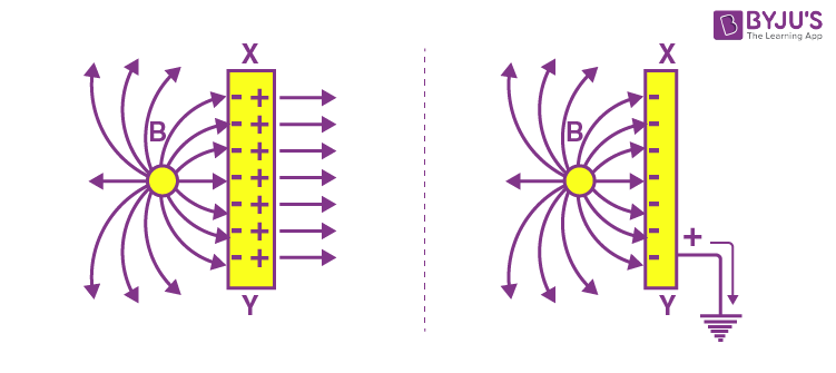
An earthed conductor acts as a screen or a shield against the electric field. If we place a metal screen XY near a charged body B, the resultant electrostatic field due to electrostatic induction is as shown in figure (a). But when the conductor XY is earthed, the free induced positive charge on it flows to the earth, and with it disappears the lines of force emanating from it, as shown in figure (b).
Conductors without Cavity
We know that a good electrical conductor, such as copper, contains charges (electrons) that are not bound to any atom and are free to move about within the material. When there is no net motion of charge within the conductor, the conductor is in electrostatic equilibrium. A conductor in electrostatic equilibrium has the following properties.
1. The electric field is zero everywhere inside the conductor.
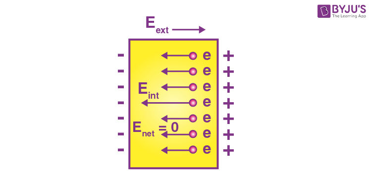
Consider a conducting slab placed in an external field Eext in electrostatic equilibrium; the electric field inside the conductor must be zero. If this were not the case, the free charges would accelerate under the action of the field.
Before the external field is applied, the electrons are uniformly distributed throughout the conductor. When the external field is applied, the free electrons accelerate to the left, causing a build-up of negative charge on the left surface (excess electrons) and of positive charge on the right (from where electrons have been removed.)
These charges create their own internal electric field (Eint), which opposes the external field. The surface charge density increases until the magnitude of the internal electric field equals that of the external electric field, giving a net field (Enet) of zero inside the conductor.
In good conductors, the time it takes the conductor to reach equilibrium is of the order of 10–16 s, which for most purposes, can be taken as instantaneous.
It should be noted that induced charges appearing on the surfaces are equal and opposite.
2. The electric field must be normal at every point to the surface of the charged conductor.
If electric field E had a tangential component, the free charge would move along the surface, creating surface currents, and the conductor would not be in equilibrium.
3. Any charge on an isolated conductor resides on its surface.
Consider a Gaussian surface just inside a charged conductor carrying charge q. Since there is no electric field inside the conductor (and hence the Gaussian surface) from Gauss’s law,
Thus, there is no charge inside the conductor, and the excess charge q resides on its surface, as shown in the figure. However, Gauss’s law does not tell us how this charge is distributed on the surface. This principle that there are no charges on the inner surface of a charged body, can be used to transfer the charge from a sphere to a previously charged conductor.
We do this by inserting the charged sphere into the cavity of the conductor and touching its inner surface. The charge from the sphere will then be completely transferred to the outer surface of the conductor, and the sphere will be completely discharged. Van de Graaff generator is based on this property.
4. The electric field just outside a charged conductor has a magnitude σ/ϵ0, where σ is the charge per unit area at that point.
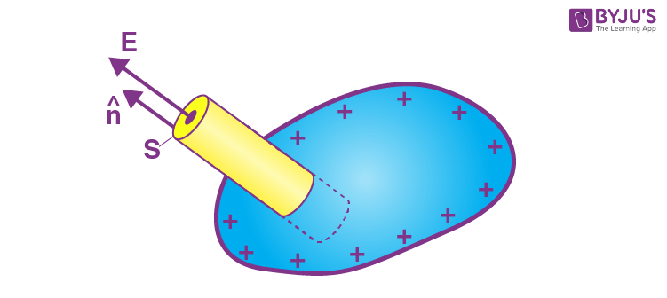
We can use Gauss’s law to relate the electric field just outside the surface of a charged conductor in equilibrium to the charge E distribution on the conductor. To do this, it is convenient to draw a Gaussian surface in the shape of a small cylinder with ends parallel to the surface, as shown in the figure. A part of the cylinder is just outside the conductor, and a part is inside it.
(i) There is no flux through the face on the inside of the cylinder because E = 0 inside the conductor.
(ii) There is no flux through the cylindrical part of the Gaussian surface because E is tangent to this part. Hence, the net flux through the Gaussian surface is ES, where E is the electric field just outside the conductor.
Applying Gauss’s law to this surface,
Or
Since the electric field is normal to the surface,
Where, n is a unit vector normal to the surface in the outward direction.
It should be noted that:
(i) Equation (2) is true for both signs of σ.
(ii) For σ > 0,
(iii) Further, equation (2) agrees with the results already obtained and is known as Coulomb’s theorem.
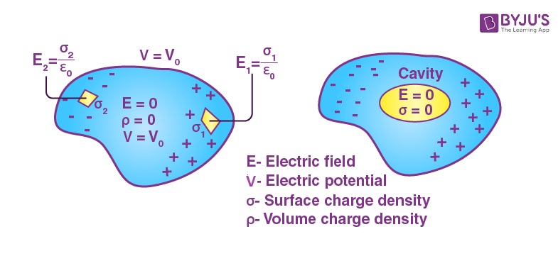
Conductors with Cavity
Consider a conductor of arbitrary shape containing a cavity, as shown in the figure.
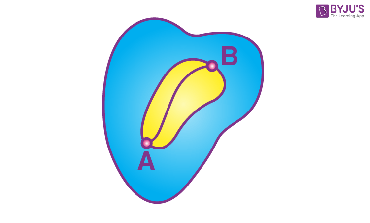
The electric field inside the cavity must be zero, regardless of the charge distribution on the outside surface of the conductor. Furthermore, the field in the cavity is zero even if an electric field exists outside the conductor. In order to prove this point, we use the fact that every point on the conductor is at the same potential, and therefore any two points, A and B, on the surface of the cavity must be at the same potential.
A cavity surrounded by the conducting walls is a field-free region as long as there are no charges inside the cavity.
Electrostatic Shielding
The above result has some interesting applications. For example, it is possible to shield an electronic circuit or even an entire laboratory from the external field by surrounding it with conducting walls. Shielding is often necessary when performing highly sensitive electrical measurements.
Electrostatic Potential
The electrostatic potential is constant throughout the volume of the conductor and has the same value (as inside it) on its surface.
Since (i) E = 0 inside the conductor and (ii) E has no tangential component on the surface, no work is done in moving a test charge: (a) within the conductor (b) on its surface. In other words, there is no potential difference between any two points (i) inside or (ii) on the surface of the conductor. In case the conductor is charged, the electric field normal to the surface exists, which means the potential is different for the surface and for a point outside the surface.
Since inside a conductor, E = 0 and dV / dr = 0 (as E = – dV/dr), thus, V = constant. It means that for all points inside a charged conductor, potential (V) is the same.
On an irregularly shaped conductor, charge tends to accumulate at locations where the radius of curvature of the surface is the smallest, that is, at sharp points.
Some of the important electrostatic properties of conductors are summarised in the figure.
Distribution of Charges on the Conductors
The distribution of charge on the surface of a conductor is described by surface charge density (σ) which is the charge per unit area of the conductor.
If the charge is uniformly distributed and q is the charge present in area A, then the surface density of charge,
σ = q/A …. (1)
In case the charge is not uniformly distributed,
σ = Δq/ΔA …. (2)
Where, Δq is the amount of charge on so small an area ΔA over which the distribution of charge can be considered uniform.
Relationship between Surface Charge Density and Curvature of the Surface
The potentials at the surfaces of spherical conductors A and B of radii r1 and r2 and carrying charges q1 and q2 on their surfaces are given by
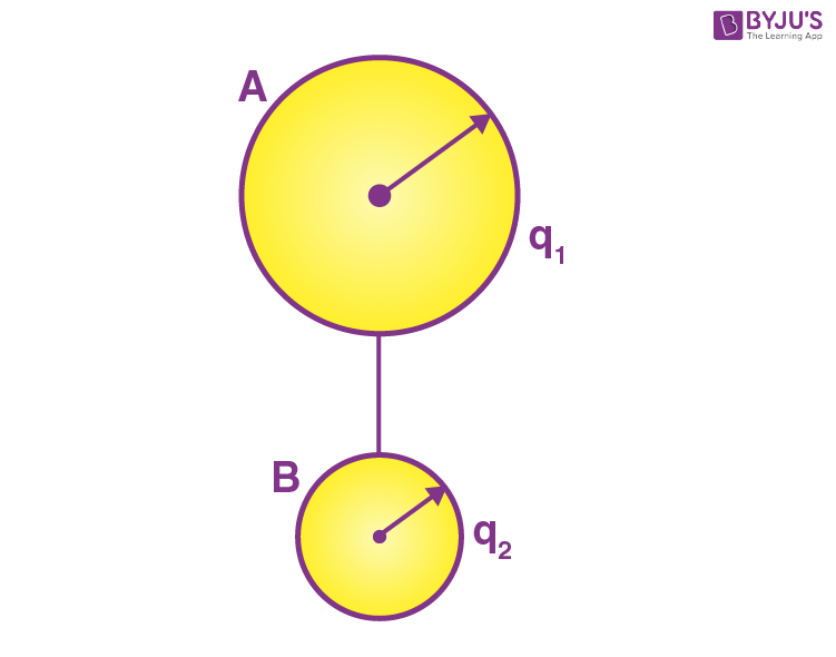
When the spheres are joined by a wire, the charge flows from one sphere to the other till they are at the same potential, i.e.,
If E1 and E2 are the electric fields at the surfaces of the spheres, then
Let σ1 and σ2 be the surface densities of charge for the two spheres. Since the charge is distributed uniformly on the surface of the conducting spheres,
Thus, the surface density of the charge is inversely proportional to the radius of the curved surface. We know that the greater the radius, the smaller the curvature. In this, the surface density of change is directly proportional to the curvature of the surface. This explains as to why the surface density of charge on the sharp and pointed ends of a conductor is greater than that on its flatter portions.
Representation of Surface Density of Charge
We already know that the charge always resides on the surface of a conductor. But the distribution of charge depends upon the shape of the surface of the conductor.
The distribution of charge on the surface of a conductor is shown by drawing a dotted line around it. The distance of this dotted line from any point on the surface represents the surface density of charge at that point.
Since the surface density of charge is directly proportional to the curvature, at a point where the conductor has a large curvature, the distance between the point of the conductor and the dotted line is also large. We represent the charge distribution due to conductors of different shapes below.
We have shown a spherical conductor, a cylindrical conductor, a pear-shaped conductor, an oval conductor, a square conductor and a rocket-shaped conductor in Figures (a), (b), (c), (d), (e) and (f), respectively.
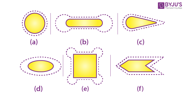
From all these figures, the following points of interest emerge.
(i) Wherever the curvature is uniform, the surface density is also uniform.
(ii) At edges and corners, where the curvature is maximum (i.e., the radius is minimum), the surface density of charge is also maximum.
(iii) There is no charge inside the conductor.
Solved Questions
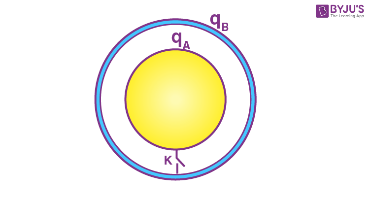
1. Two metallic concentric shells of radii rA and rB are given charges qA and qB, respectively.
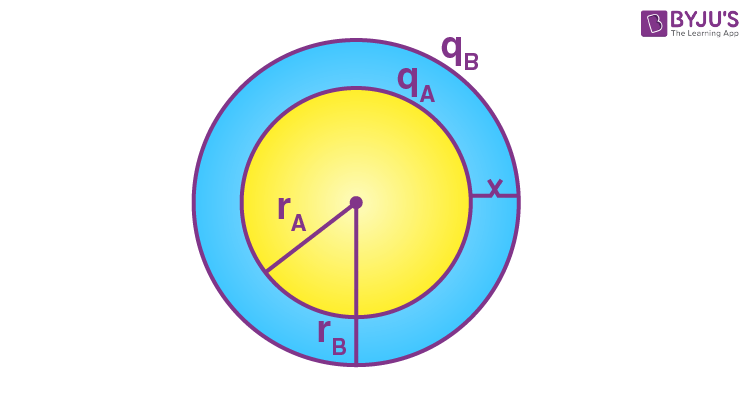
Initially, both of the shells are not connected. If we connect two shells by a conducting wire, what happens to the potential difference between them? And charges on them?
Solution:
Case (I): Key (K) is open
The potential of shell A is due to both the charges qA and qB
Similarly, the potential of B,
Now, the potential difference between shells A and B is,
This tells us ΔV is independent of charge on the outer shell, and the only function of the inner shell charge potential of the inner shell is always greater than the potential of the outer shell.
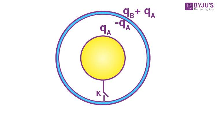
Case (II) : [switch (K) is closed]
If switch (k) is closed, then ΔV = 0
It is only possible when qA = 0, which means the whole of charge on the inner shell is transferred to the outer shell. If inner and outer shells are connected, they cannot hold the charge on the shells. Charges on the inner shell always go to the outer shell.
2. Two concentric spherical shells of A and B having charges qA, qB and radii rA and rB, respectively; if the key (k) is closed, what happens to the final charge? Distribution of the system?
Solution:
If we bring a conducting object neat to another conducting object, induction will take place.
Induction of charges:
Charges on the inner shell qA will pull out (-qA) the amount of charges from the outer shell inwards. Similarly, it pushes out (+qA) the amount of charge from the outer shell to the outwards.
Before the key is closed,
When the key is closed
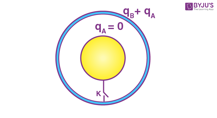
When the key is closed, the charge given to the inner shell will become zero, which goes to the outer shell. This happens because it wants to shield the electric field.
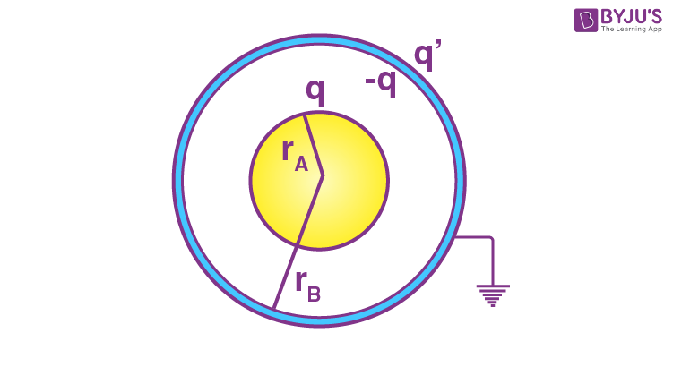
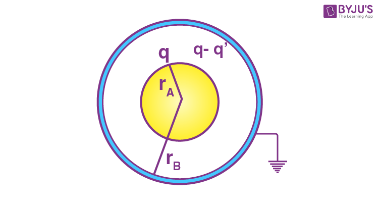
3. Consider two concentric spherical shells, A and B, of charges qA = q0, qB = 0, and radii rA and rB, respectively. If the outer sphere is grounded, what happens to the final charge distribution?
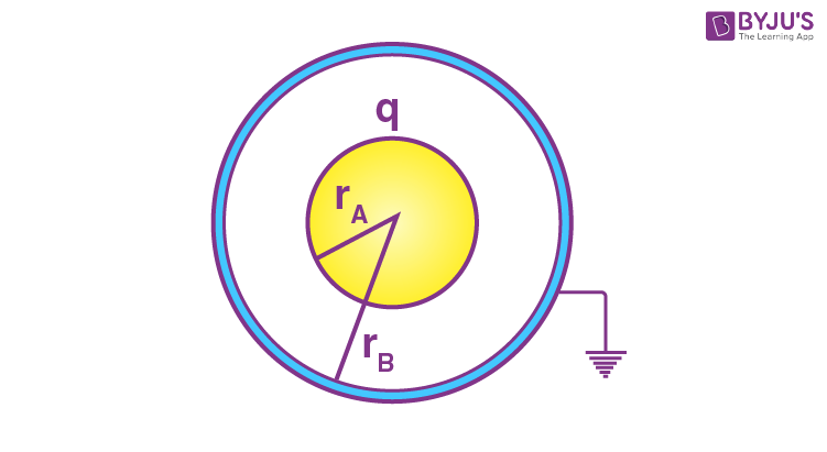
Solution:
Shell A is an isolated system (it is not connected to anything else)
But shell B is non-isolated. It is connected to the ground.
For the isolated system, 🡺 the charge must be conserved.
For the non-isolated system, 🡺the charge cannot be conserved.
Grounding
Grounding is the reference level for the potential of the system. We will take grounding means zero reference.
Level of the potential.
(In mechanics ground PE of the system is zero, in electrostatic grounding means the potential (v = 0) of the system is zero).
It does not mean all the charges go into the ground; sometimes, it may be and may not be. We will measure the charge of the grounded object by taking potential (V = 0). By writing the v = 0 equation and solving it, we will get the charge of the grounded shell.
For grounded objects, the outer surface charge is always taken as q’. The inner charge will be a bounded charge (or) induced charge by the inner ring.
Two-facing surfaces will always have an equal and opposite charge because they are bounded surfaces.
If we write the equation (v = 0) for grounded objects by all the charges present in the system,
Hence, the final charge distribution will become
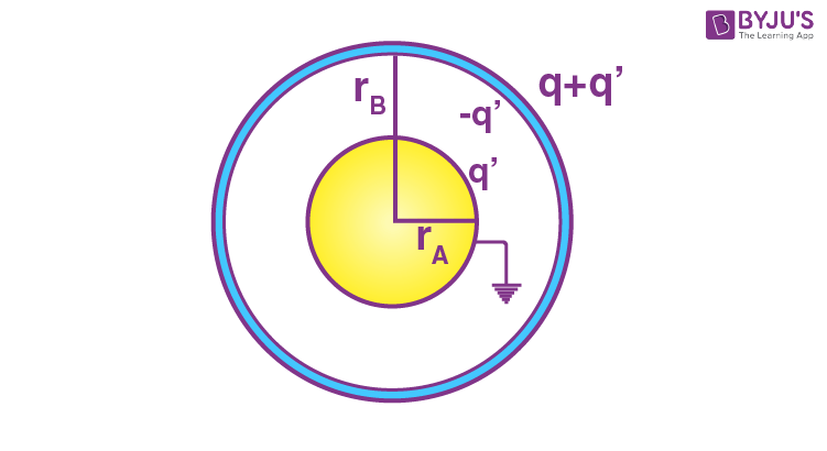
4. Two shells of A and B having charges qA = 0 and qB = q and radii rA and rB
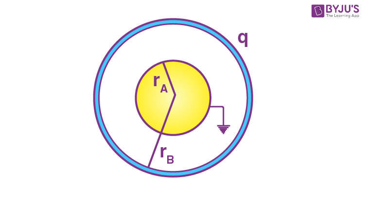
Respectively, find the final charge distribution if the inner shell is grounded.
Sol:
A single charge (q) on the outer shell cannot make the potential of the system zero to make the potential of the system zero. Some charges have to come from the ground q’ amount of charges on the inner shell because of grounding this q’ will push out q’ amount in outer shell charge outwards and pulls (-q’) amount of charge on the outer shell to inwards.
So, the final charge distributions become,
We put q1 for a grounded shell. We know it cannot hold charge conservation, so put q’ charge on the grounded shell. To find out, we have written an equation (V = 0) of the grounded shell by all the others in the system.
Grounding only ensures the total potential of the system should be zero.
Electrostatics – Electric Field Lines and Electric Flux

Electrostatics – Electric Field and Electric Dipole

Frequently Asked Questions on Shielding
What are the applications of electrostatic shielding?
In cars, the metallic body works as an electrostatic shield. The metallic body protects the person seated inside from lightning.
The wires carrying audio signals are protected by electrostatic shielding.
Lineman wear suits made from Faraday’s cage to protect themselves from electrocution.
How is an object shielded from a strong electrostatic field?
Inside a metallic conductor, the electric field is zero. Objects can be placed in a hollow metallic structure to shield them from the strong electrostatic fields.
Why do charges accumulate at the points?
The charges present on the surface of a body are similar (i.e., either positive or negative) and, as such, repel each other. Thus, the charges try to go as far away from each other as the shape of the body permits. Corners and edges, being at maximum distance, have the maximum charge density. In other words, these are the ‘hot beds’ of charge.
What is shielding in Physics?
In Physics, electrostatic shielding is blocking the electric field from entering a certain region in space.

Comments