The Carnot cycle was first developed in the year 1824 by a French physicist named Sadi Carnot. It is an ideal cycle that basically laid the foundation for the second law of thermodynamics. The Carnot cycle also brought up the concept of reversibility.
In this lesson, we will look at all the aspects of the Carnot cycle as well as understand some key concepts.
Carnot’s Theorem
From the second law of thermodynamics, two important results are derived, where the conclusions are taken together to constitute Carnot’s theorem. It may be stated in the following forms:
(a) “No engine can be more efficient than a perfectly reversible engine working between the same two temperatures”.
(b) “The efficiency of all reversible engines, working between the same two temperatures is the same, whatever the working substances”.
Carnot Cycle Proof
First Part
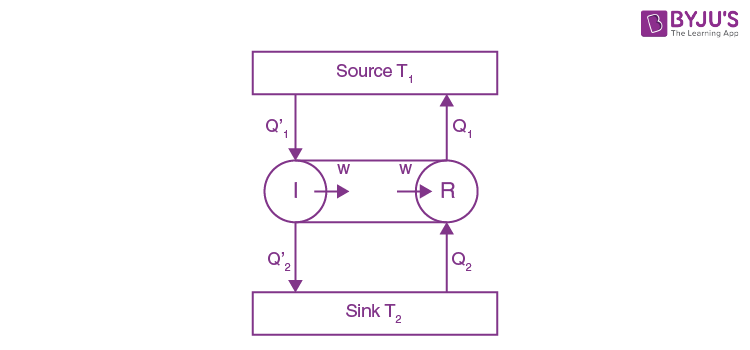
To prove the first part of the theorem, we consider two engines, R and I, working between the temperatures T1 and T2, where T1 > T2 (Fig.). Of these two engines, R is reversible, and I is irreversible.
Suppose I is more efficient than R. In each cycle, R absorbs the quantity of heat Q1 from the source at T1 and rejects the quantity of heat Q1 from the source at T1 and rejects the quantity of heat Q2 to the sin at T2.
Similarly, in each cycle, I absorbs the quantity of heat Q1’ from the source at T1 and gives up the quantity of heat Q2’ to the sink at T2.
Let the two engines do the same amount of work W in each cycle. According to the assumption, I is more efficient than R.
Therefore,
Or
Or
And
Or
Now, because
Therefore,
Now, if the two engines are coupled together so that I drives R backwards and suppose they use the same source and sink, the combination forms a self-acting machine in which I supplies external work W and R absorbs this amount of work in its reverse cycle. I, in its cycle, absorbs heat Q’ from the source and gives up heat Q2’ to the sink. R, in its reverse cycle, absorbs heat Q2 from the sink and gives up heat Q1 to the source.
The net result of the complete cycle of the coupled engines is given by,
Gain of heat by the source at T1 = Q1 – Q1’
Loss of heat by the sink at T2 = Q2 – Q2’
External work done on the system = 0
Thus, the coupled engines forming a self-acting machine, unaided by any external agency, transfer heat continuously from a body at a low temperature to a body at a higher temperature.
This conclusion is contrary to the second law of thermodynamics, according to which, in a cyclic process, heat cannot be transferred from one body to another at a higher temperature by a self-acting machine. Hence, our assumption is incorrect, and we can conclude that no engine can be more efficient than a perfectly reversible engine working between the same temperatures.
Second Part
The second part of the theorem may be proved by the same arguments as before. For this purpose, we consider two reversible engines, R1 and R2 and assume that R2 is more efficient than R. Proceeding in the same way, we can show that R2 cannot be more efficient than R1. Therefore, all reversible engines working between the same two temperatures have the same efficiency.
Thus, the efficiency of a perfectly reversible engine depends only on the temperatures between which the engine work and is independent of the nature of the working substance.
Carnot’s Ideal Heat Engine
In 1824, the French engineer Sadi Carnot conceived a theoretical engine which is free from all practical imperfections. Such an engine cannot be realised in practice. It has maximum efficiency, and it is an ideal heat engine. Sadi Carnot’s heat engine requires the following important parts:
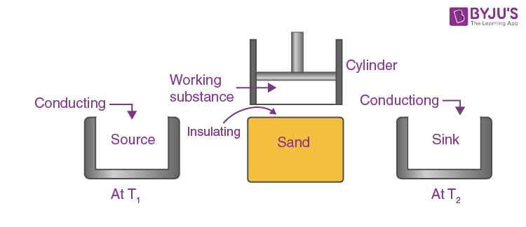
1. A cylinder having perfectly non-conducting walls, a perfectly conducting base, and is provided with a perfectly non-conducting piston which moves without friction in the cylinder. The cylinder contains one mole of perfect gas as the working substance.
2. Source: A reservoir maintained at a constant temperature T1 from which the engine can draw heat by perfect conduction. It has an infinite thermal capacity, and any amount of heat can be drawn from it at constant temperature T1.
3. Heat insulating stand: A perfectly non-conducting platform acts as a stand for adiabatic processes.
4. Sink: A reservoir maintained at a constant lower temperature T2 (T2 < T1) to which the heat engine can reject any amount of heat. The thermal capacity of the sink is infinite, so its temperature remains constant at T2, no matter how much heat is given to it.
Carnot’s Cycle and Its Stages
In order to obtain a continuous supply of work, the working substance is subjected to a cycle of quasi-static operations known as the Carnot cycle. The cycle, when it acts as a heat engine, consists of various steps, which are as follows.
Isothermal Expansion
The cylinder is first placed on the source so that the gas acquires the temperatures T1 of the source. It is then allowed to undergo quasi-static expansion. As the gas expands, its temperature tends to fall. Heat passes into the cylinder through the perfectly conducting base, which is in contact with the source. The gas, therefore, undergoes slow isothermal expansion at the constant temperature T1.
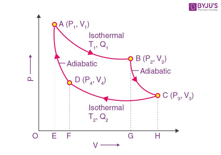
Let the working substance during isothermal expansion go from its initial state A (P1, V1, T1) to state B (P2, V2, T1) at constant temperature T1 along AB. In this process, the substance absorbs heat Q1 from the source at T1 and does work W1 given by,
Adiabatic Expansion
The cylinder is now removed from the source and placed on the insulating stand. The gas is allowed to undergo slow adiabatic expansion, performing external work at the expense of its internal energy until its temperature falls to T2, the same as that of the sink.
This operation is represented by the adiabatic BC, starting from state B (P2, V2, T1) to state C (P3, V3, T2). In this process, there is no transfer of heat, the temperature of the substance falls to T2, and it does some external work W2, given by,
Because, during adiabatic process,
Isothermal Compression
The cylinder is now removed from the insulating stand and is placed on the sink, which is at a temperature of T2. The piston is now very slowly moved inwards so that the work is done on the gas. The temperature tends to increase due to heat produced by compression since the conducting base of the cylinder is in contact with the sink, the heat developed passes to the sink, and the temperature of the gas remains constant at T2. Thus, the gas undergoes isothermal compression at a constant temperature of T2 and gives up some heat to the sink.
This operation is represented by the isothermal CD, starting from state (P3, V3, T2) to state D (P4, V4, T2). In this process, the substance rejects heat Q2 to the sink at T2, and work W3 is done on the substance given by,
(- ve sign indicates that work is done on the working substance)
Adiabatic Compression
The cylinder is now removed from the sink and again placed on the insulating stand. The piston is slowly moved inwards so that the gas in adiabatic compression is continued till the gas comes back to its original condition, i.e., state A (P1, V1, T1), thus completing one full cycle.
This operation is represented by adiabatic DA, starting from D (P4, V4, T2) to the final state A (P1, V1, T1). In this process, work W4 is done on the substance and is given by,
(- ve sign indicates that work is done on the working substance. Since W2 and W4 are equal and opposite, they cancel each other.)
Work Done by the Engine Per Cycle
During the above cycle, the working substance absorbs an amount of heat Q1 from the source and rejects Q2 to the sink.
Hence, the net amount of heat absorbed by the gas per cycle
= Q1 – Q2
The net amount of work done by the engine per cycle
= W1 + W2 + W3 + W4
= W1 + W3 because
From the graph, the net work done per cycle = area ABGEA + area BCHGB – area CHFDC – area DFEAD
= area ABCDA
Thus, the area enclosed by the Carnot’s cycle consisting of two isothermals and two adiabatic gives the net amount of work done per cycle.
In the cyclic process,
Net heat absorbed = Net work done per cycle.
Q1 – Q2 = W1 + W3
Since the points A and D lie on the same adiabatic Da,
Similarly, points B and C lie on the same adiabatic BC
Therefore,
From equations (4.20) and (4.21),
Or
Or
Substituting in equation (4.19), we get,
Net work done =
Efficiency
The efficiency of the heat engine is the rate of the quantity of heat converted into work (useful output) per cycle to the total amount of heat absorbed per cycle.
From the equation, we conclude that efficiency depends only upon the temperature of the source and sink, and is always less than unity. The efficiency is independent of the nature of the working substance.
From the equation,
Again, the efficiency is minimum or zero, then T1 = T2, i.e., the temperature of the source is equal to the temperature of the sink, then η = 0, i.e., the engine does not work.
The Carnot heat engine is perfectly reversible. It can be operated in the reverse direction also. Then, it works like a refrigerator. The heat Q2 is taken from the sink, and external work is done on the working substance and heat Q2 is rejected to the source at a higher temperature (principle of a refrigerator).
Moreover, in the Carnot heat engine, the process of isothermal and adiabatic expansions and compressions are carried out very-very slowly, i.e., quasi-static. This is an ideal case. Any practical engine cannot satisfy these conditions. Therefore, all practical engines have an efficiency less than the Carnot engine.
Frequently Asked Questions on Carnot Cycle
How to calculate Carnot cycle efficiency?
The efficiency of a heat engine is defined as the ratio of the heat converted into work in a cycle to the total heat supplied to the source.
η = Work done/Heat supplied
= (Q1 – Q2)/Q1
= 1 – (Q2/Q1)
If T1 and T2 are the temperatures of the source and the sink, respectively, then (Q2/Q1) = (T2/T1).
Therefore, η = 1 – (T2/T1)
Why is the Carnot cycle not practically possible?
The real engines are not reversible due to reasons like heat transfer, friction, etc., whereas the Carnot engine is reversible. In the Carnot cycle, the reverse process takes place very slowly, but real engines work faster. The temperature of the source and the sink is kept constant in the Carnot cycle, but in a real engine, heat transfer will occur only if there is a difference in temperature between the source and the sink.
When will the efficiency of the Carnot engine be maximum?
The efficiency of the Carnot engine is
η = 1 – (T2/T1)
T1 and T2 are the temperatures of the source and the sink, respectively.
The efficiency of the engine will be 100% only if the temperature of the sink T2 = 0.
Is the Carnot cycle reversible?
Yes, the Carnot cycle is reversible.

Comments