In this article, we will explore circuit diagrams in a comprehensive way, understanding their purpose and what they consist of. Examples of circuit diagrams that showcase different circuit configurations and the symbols used in them are explained. We will also take a closer look at the components we often come across in circuit diagrams, such as resistors, capacitors, and switches, and explain how they are represented with symbols. By the end of this article, you’ll have a solid understanding of circuit diagrams and how they represent electrical circuits.
| Table of Contents |
What is a Circuit Diagram?
A circuit diagram, also known as an electrical diagram, elementary diagram, or electronic schematic, is a graphical representation that simplifies an electrical circuit. It serves as a visual tool for the design, construction, and maintenance of electrical and electronic equipment. By utilising either images of distinct components or standard symbols, a circuit diagram presents a simplified depiction of the circuit’s elements and their interconnections. This enables electricians and technicians to easily understand the relative positions of the components and their relationships within the circuit.
Reading a Circuit Diagram
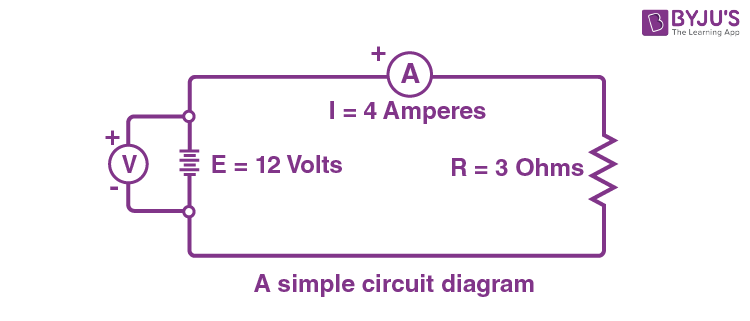
To illustrate the concept of circuit diagram, refer to the following figure showcasing a simple circuit diagram.

The given circuit diagram consists of components such as a voltage source, a voltmeter, an ampere, and a resistor.
In the next few sections, we will explore how to identify and interpret symbols for voltage sources, resistors, capacitors, inductors, switches, and more. By understanding these symbols and their meanings, we can understand how different elements in a circuit are connected and how they function together.
Components of Circuit Diagram
In this section, let us learn about some important circuit diagram symbols.
Electric cell
An electric cell is represented by a long and short parallel line. The long line indicates the positive terminal, and the short line represents the negative terminal.

Battery
A battery, which consists of multiple electric cells connected together, is represented by two or more electric cell symbols arranged in a series. The positive terminal of one cell is connected to the negative terminal of the next cell.

Switch
A switch is represented by a line with a gap or break in it. When the switch is closed or turned on, the gap is bridged, indicating the flow of current through the switch. When the switch is open or turned off, the gap remains, indicating the interruption of current flow.

Wire Joint
A wire joint is indicated by a dot or a small solid circle where two or more wires intersect or connect. It signifies that the wires are electrically connected at that point.

Wires crossing without joining
When two wires cross each other in a circuit diagram without a dot or circle at the intersection, it means that the wires do not make electrical contact. They are simply crossing paths without being connected.

Electric Bulb
An electric bulb, or lamp, is represented by a circle with a cross inside it. The cross signifies the filament or light-emitting part of the bulb.

Resistor
A resistor is represented by a zigzag line. t is used to limit the flow of electric current in a circuit.

Variable Resistor
A variable resistor, also known as a rheostat or potentiometer, is represented by a resistor symbol with an arrow or a diagonal line passing through it. The arrow or line indicates that the resistance value can be adjusted or varied.

Inductor
An inductor, which is a passive component that stores energy in the form of a magnetic field, is typically represented by a coil-shaped symbol. It consists of several loops or turns of wire.

Fixed Capacitor
A fixed capacitor is represented by two parallel lines, which signify the plates of the capacitor, with a space between them. The fixed capacitor symbol does not include any specific polarity markings since it is not polarized.

Polarized Capacitor
A polarized capacitor, such as an electrolytic capacitor, has a specific polarity and must be connected in a specific orientation in the circuit. The symbol for a polarized capacitor includes a curved line or an arrow, indicating the positive terminal, and a straight line, representing the negative terminal.

Ammeter
An ammeter is a measuring instrument used to measure electric current. It is represented by a circle with the letter “A” inside.

Voltmeter
A voltmeter is a measuring instrument used to measure voltage or potential difference. A voltmeter is represented by a circle with the letter “V” inside.

Circuit Diagram Examples
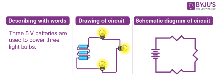
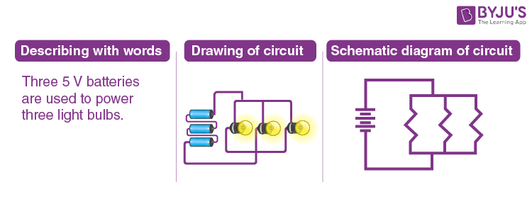
Example: Three 5 V batteries are used to power a circuit containing three light bulbs.

To represent the verbal description of the circuit, we can draw three light bulbs and connect them to three cells using wires. The circuit diagram assumes that the light bulbs are connected in series. However, it’s important to note that they can also be connected in parallel or in different combinations.

This example highlights the two common types of connections found in electric circuits: series and parallel. When a circuit has multiple components, such as resistors, they can be connected either in series, where the current flows through them in a sequential manner, or in parallel, where the current splits and flows through each component simultaneously.
If you are interested in delving deeper into circuit analysis techniques and enhancing your understanding of electrical circuits, we recommend exploring the following articles
- Thevenin’s Theorem
- Superposition Theorem
- Nodal Analysis
- Mesh Analysis
- Resistors in Series and Parallel.
If you’re preparing for your Class 10 Science Board exam, this session is a must-watch, as it covers all the crucial concepts from Chapter 10, Electricity.

Frequently Asked Questions – FAQs
What is a Circuit Diagram?
What is the purpose of a circuit diagram?
What symbols are used in a circuit diagram?
What is a simple circuit diagram?
What is the difference between a pictorial and a schematic diagram?
Enhance your understanding of Electricity in Class 10 Science by watching this video and solving previous years’ questions.

Stay tuned to BYJU’S to learn interesting physics topics with the help of interactive video lessons.

good