Magnetism is a physical characteristic caused by magnetic fields that produce attractive and repulsive effects on other objects. A magnetic field is generated by electric currents and magnetic moments of particles and influences other currents and magnetic moments. Ferromagnetic materials, which are strongly drawn to magnetic fields and can become permanent magnets themselves, are the most well-known materials that exhibit magnetism. Only a limited number of substances are ferromagnetic, including iron, cobalt, nickel and their alloys, which are the most common. The less common ferromagnetic substances include the rare-earth metals neodymium and samarium. Ferro- refers to iron as the permanent magnetism that was first found in lodestone, a type of iron ore called magnetite (Fe3O4).
A magnetic field is a field of vectors representing magnetism’s impact on moving electric charges, electric currents, and magnetic materials. A force perpendicular to both the velocity and magnetic field is experienced by a moving charge in a magnetic field. A permanent magnet’s magnetic field attracts ferromagnetic materials like iron and other magnets. Nonuniform magnetic fields can also apply tiny forces to “nonmagnetic” materials through paramagnetism, diamagnetism, and antiferromagnetism, but these forces are usually so weak that they can only be measured with laboratory equipment. Magnetised materials are surrounded by magnetic fields generated by electric currents in electromagnets and changing electric fields. As the strength and direction of magnetic fields can vary in different locations, they are described mathematically with a vector field function assigning a vector to each point in space.
Magnetic fields are produced by the movement of electric charges and the inherent magnetic moments of particles connected to their spin, a fundamental quantum property. Magnetic and electric fields are related, and both are part of the electromagnetic force, one of nature’s four fundamental forces. Magnetic fields are widely utilised in modern technology, especially in electrical engineering and electromechanics. Rotating magnetic fields are applied in electric motors and generators. The study of magnetic fields in electrical devices like transformers is called magnetic circuits. The Hall effect shows the presence of charge carriers in a material through magnetic forces. The Earth generates its own magnetic field, protecting the ozone layer from solar wind and crucial for compass navigation.
Important Questions For Class 12 – Physics – Chapter 4 – Moving Charges and Magnetism are provided here. Students must go through these questions and solve them to prepare for their Physics papers. They can also refer to these questions for quick revision. These questions are more likely to be asked in the exam; hence, students must practise them thoroughly.
Very Short Answer Type Questions
1. How does the radius of the path of a charged particle moving in a cyclotron change when the radio frequency field’s frequency is doubled?
(a) It will be halved.
(b) It will be doubled.
(c) It will remain unchanged.
(d) It will be increased by four times.
Answer: (c) It will remain unchanged.
2. Which of the following statements about a cyclotron is not true?
(a) A cyclotron is a device that uses high energies to accelerate ions or charged particles.
(b) Cyclotron combines electric and magnetic fields to accelerate charged particles and increase their energy.
(c) The cyclotron works by utilising the principle that the time it takes for an ion to complete one revolution is not affected by its speed or the radius of its orbit.
(d) In a cyclotron, the path of charged particles and ions is not fixed and can be arbitrary.
Answer: (d) In a cyclotron, the path of charged particles and ions is not fixed and can be arbitrary.
3. If an electron is travelling with velocity ν, it generates a magnetic field B, then
(a) the direction of field B will align with the direction of velocity ν.
(b) the direction of field B will be in the opposite direction to the direction of velocity ν.
(c) the direction of field B will be at a right angle to the direction of velocity ν.
(d) the direction of field B is independent of the direction of velocity ν.
Answer: (c) the direction of field B will be at a right angle to the direction of velocity ν.
4. If the magnetic compass needle is brought close to a straight wire bearing current, then
(I) the straight wire results in a significant deviation of the compass needle.
(II) The needle tangentially aligns to an imaginary circle whose centre is the straight wire and whose plane is perpendicular to the wire.
(a) (II) is correct
(b) (I) is correct
(c) neither (I) nor (II) is correct
(d) both (I) and (II) are correct
Answer: (d) both (I) and (II) are correct
5. Which statement about magnetic forces is correct?
(a) Magnetic forces always obey Newton’s third law.
(b) Magnetic forces do not follow Newton’s third law.
(c) Magnetic forces adhere to Newton’s third law when the current is very high.
(d) Magnetic forces comply with Newton’s third law in a low magnetic field environment.
Answer: (b) Magnetic forces do not follow Newton’s third law.
6. Converting a moving coil galvanometer into a voltmeter is achieved by
(a) placing a high resistance in series.
(b) placing a low resistance in parallel.
(c) placing a high resistance in parallel.
(d) placing a low resistance in series.
Answer: (a) placing a high resistance in series.
7. Converting a moving coil galvanometer into an ammeter is done by
(a) placing a high shunt resistance in series.
(b) placing a low shunt resistance in parallel.
(c) placing a low resistance in series.
(d) placing a high resistance in parallel.
Answer: (b) placing a low shunt resistance in parallel.
Short Answer Type Questions
1. Verify that the cyclotron frequency = eB/m has the correct dimensions of [T]-1
Solution:
When a charged particle travels normal to the magnetic field, then
2. Show that a force that does no work and is a velocity-dependent force.
Solution:
Work is a scalar product of displacement and force. Hence work done at any instant is given by the following formula:
Where displacement is given as:
According to the question, the work done by the force is:
This shows that the angle between force and velocity will be 90o. If the direction of velocity changes, then the direction of the force will also vary.
3. The magnetic force depends on v, which depends on the inertial frame of reference. Does then the magnetic force differ from inertial frame to frame? Is it reasonable that the net acceleration has a different value in different frames of reference?
Solution:
The magnetic force relies on vector v, which depends on the inertial reference frame. Magnetic force on a charged particle,
Thus, the magnetic force is velocity-dependent. It varies from one inertial frame to another inertial frame.
4. Describe the motion of a charged particle in a cyclotron if the frequency of the radio (rf) field was doubled.
Solution:
When the frequency of the radio frequency (rf) field is doubled, then the resonance condition is violated, and the time period of the radio frequency (rf) field is halved.
Therefore, the duration in which a particle completes half revolution inside the dees, radio frequency completes the cycle. As a result, particles will accelerate and decelerate alternatively.
5. Two long wires carrying current I1 and 12 are arranged as shown in the figure. The one carrying current I1 is along the x-axis. The other carrying current, I2 is along a line parallel to the y-axis given by x = 0 and z =d. Find the force exerted at 02 because of the wire along the x-axis.

Solution:
Magnetic field at the point O2 due to current I1 in long wire along the x-axis is
It will be along the y-axis. Since the second wire is along the y-axis, the angle between the direction of
Force on the wire existing along the y-axis is,
Long Answer Type Questions
1. A current carrying loop consists of 3 identical quarter circles of radius R, lying in the
positive quadrants of the x-y, y-z and z-x planes with their centres at the origin, joined
together. Find the direction and magnitude of B at the origin.
Solution:
Draw a rough diagram.

The equation used is
It is given that
The electric current in circular arc = I, Radius = R
The magnetic field at the origin point due to the electric current carrying arc existing in x-y plane:
Likewise, the Magnetic field at the origin point due to the electric current circular arc existing in the y-z plane:
Likewise, the magnetic field at origin due to the electric current carrying a circular arc existing in the y-x plane:
The total vector sum of the magnetic field at the origin point due to each quarter circle,
2. A charged particle of charge e and mass m is moving in an electric field E, and magnetic field B. Construct dimensionless quantities and quantities of dimension [T]-1.
Solution:
No dimensionless quantity made using the given quantities. In the case of a charged particle travelling normally to the magnetic field, the magnetic Lorentz forces lend the required circular or centripetal force for revolution.
By simplifying the equation, we get,
The dimensional form of angular frequency
3. An electron enters with a velocity v = Vo i into a cubical region (faces parallel to coordinate planes) in which there are uniform electric and magnetic fields. The orbit of the is found to spiral down inside the cube in the plane parallel to the x-y plane. Suggest a configuration of fields E and B that can lead to it.
Solution:
If a charged particle is positioned in an electric field and magnetic field, then it begins moving in a spiral trajectory where magnetic field B and electric field E is perpendicular to the direction of motion. The electric field applies force on the charged particle, which results in the particle’s deceleration or acceleration and the centripetal force works due to the magnetic force. Assume that a magnetic field B = B0 exists in the area, and an electron enters with a velocity of into the cubical region.
Using magnetic Lorentz force, the net force on the electron is represented by
The orbit of the electron circles around down inside the cube in the plane parallel to the x-y plane. So, E should be along the x-axis, and magnetic field B should be along the +z direction.
(where E0 > 0)
4. Do magnetic forces obey Newton’s third law? Verify for two current elements dl1 – dl i (unit vector) located at the origin and dl2 = dl j (unit vector) located at (O, R, O). Both carry current I.
Solution:
Here, it is required to find the magnetic field’s direction due to one wire at the point on a different wire, then the magnetic force on the current bearing wire.
As per Biot-Savart’s law, the magnetic field is parallel to idl × r, and idl is the current bearing element which has its direction along the current flow’s direction.
In the case of the magnetic field direction, at dl2, positioned at (0, R, 0) due to wire dl s represented by B || idl × r or i × j (point (0, r, 0) lies on the y-axis) and i × j = k. Therefore, the magnetic field at dl2 is along the z-direction.
The magnetic force direction exerted at dl2 due to the magnetic field of the first wire is along the x-axis.
F -i(I × ), i.e., F || (i × k) or along the -j direction.
Thus, the force due to dl1 and dl2 is non-zero.
Hence, magnetic forces do not follow Newton’s third law. But they follow Newton’s third law if the current carrying sections are placed parallel to each other.
5. A multirange voltmeter can be constructed by using a galvanometer circuit, as shown in the figure. We want to construct a voltmeter that can measure 2V, 20V and 200V using a galvanometer of resistance 10Ω and produce maximum deflection for a current of 1 mA. Find R1, R2, and R3 that have to be used.

Solution:
In this scenario,
6. A long straight wire carrying a current of 25A rests on a table, as shown in the figure. Another wire PQ of length 1m, mass 2.5g, carries the same current but in the opposite direction. The wire PQ is free to slide up and down. To what height will PQ rise?

Solution:
In this case,
In the equilibrium position,
7. A 100-turn rectangular coil, ABCD (in XY plane), is hung from one arm of a balance. A mass of 500g is added to the other arm to balance the weight of the coil. A current 4.9 A passes through the coil, and a constant magnetic field of 0.2 T acting inward (in xz plane) is switched on such that only arm CD of length 1 cm lies in the field. How much additional mass ‘m’ must be added to regain the balance?

Solution:
If the magnetic field is zero and the weight is added to one balance pan, balance the rectangular coil in the other balance pan. Then
When the current (I) is passed through the coil and the magnetic field is switched on, let ‘m’ be the mass added in a pan to counterbalance the beam. Then
8. A rectangular conducting loop consists of two wires on two opposite sides of length ‘I’ joined together by a rod of length ‘d’. The wires are each of the same material but with cross-sections differing by a factor of 2. The thicker wire has a resistance E, and the rods are of low resistance, which in turn are connected to a constant voltage source V0. The loop is placed in uniform a magnetic field B at 45o to its plane. Find τ, the torque exerted by the magnetic field on the loop about an axis through the centres of rods.
Solution:
Equation used:

Force on current bearing wire placed in a magnetic field,
The force on the thicker wire (wire 1) is
Torque on wire on wire 1 due to F1,
Torque on the wire 2 due to F2,
(A = Id = Area of loop)
9. An electron and a positron are released from (0, 0, 0) and (0, 0, 1.5R), respectively, in a uniform magnetic field, each with an equal momentum of magnitude p = e BR. Under what conditions on the directions of momentum will the orbits be non-intersecting circles?
Solution:
Since B is along the x-axis, for a circular orbit, the memento of the two particles is in the y-z plane. Assume p1 and p2 as the moment of the electron and positron, respectively. Both of them are defined as a circle of radius R. Assume p1 makes an angle θ with the y-axis, and p2 should make the same angle. The centre of the circles should be normal to the momenta and at a distance of R.
The circles of the two shall not overlap if the length between the two centres is more than 2R.
Let d be the length between Ce and Cp.

Then,
As ‘d’ has to be larger than 2R
10. A uniform conducting wire of length 12a and resistance R is wound as a current-carrying coil in the shape of (i) an equilateral triangle of side a; (ii) a square of sides a, and (iii) a regular hexagon of sides a. The coil is connected to a voltage source V0. Find the magnetic moment of the coil in each case.
Solution:
(i) No. of turns, n = 4
(ii)
(iii)
Magnetic moment, M = nIA

11. Consider a circular current-carrying loop of radius R in the x-y plane with the centre at the origin. Consider the line integral 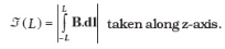
(a) Show that ζ(L) monotonically increases with L.
(b) Use an appropriate Amperian loop to show that ζ(∞)=μ0I, where I is the current in the wire.
(c) Verify directly the above result.
(d) Suppose we replace the circular coil with a square coil of sides R carrying the same current I. What can you say about ζ(L) and ζ(∞)?
Solution:
Since the circular loop carrying an electric current is lying in the x-y plane, the magnetic field is along the z-axis, in the line integral direction,
So, ζ(L) is monotonically rising with L.
(b) Take a closed amperian path PQRP as represented in the figure.
As per the Ampere circuital law, the integral of B over the closed trajectory PQRP is
If L → ∞, then the value of B → 0 (as B ∝ 1 / r3)
(c) Magnet field B at a point on the circular coil axis at a distance z from the centre of a circular coil of radius R bearing current I is
(d) If the circular coil is replaced by a square coil of side R, bearing the same current I, then
Utilising arguments as in (b)

12. A multi-range current metre can be constructed by using a galvanometer circuit, as shown in the figure. We want a current metre that can measure 10mA, 100mA and 1A using a galvanometer of resistance 10Ω and that produces maximum deflection for a current of 1mA. Find S1, S2 and S3 that have to be used.

Solution:
In this case,
In order to convert a galvanometer into an ammeter of the given current range 0 to 1, the shunt resistance needed is
Case (i)
S = S _ { 1 } + S _ { 2 } + S _ { 3 }
Case (ii)
Case (iii) If I – 1A, then S = S3
Galvanometer Resistance = (G + S1 + S2)
By inserting the value (ii) in (i), we get
From equation (ii)
From equation (iii)
Minusing equation (v) from equation (iv), we get
From equation (iv)
13. Five long wires, A, B, C, D, and E, each carrying current I, are arranged to form the edges of a pentagonal prism, as shown in the figure. Each carries current out of the plane of the paper.

(a) What will be magnetic induction at a point on the axis O? Axis is at a distance R from each wire.
(b) What will be the field if the current in one of the wires (say A) is switched off?
(c) What if the current in one of the wires (say) A is reversed?
Solution:
(a) The five wires A, B, C, D and E are positioned perpendicular to the plane of the paper, as shown in the figure. The total magnetic field induction at point O resulting from the current flowing through all five wires is zero, as it can be represented by the sides of a closed pentagon in the plane of the paper.
(b) The overall magnetic field induction at point O caused by the currents flowing through wires A, B, C, D, and E is the same as, but opposite in direction, to the magnetic field induction at O due to the current through wire A alone.
Therefore, the magnetic field induction at O due to the electric current flowing through wire A is
Therefore, the magnetic field induction at point O due to currents through the wires E, D, C, and B is
(c) When the electric current flowing wire A is reversed, then the net magnetic field induction at point O is equal to mag. The magnetic field induction due to wires E, D, C, and B is

14. What are the applications of magnetism?
Solution:
- Although we frequently use computers in our daily lives, we may not have considered the presence of a magnet inside them. Magnets play a crucial role in storing data on a hard disk and allow the computer to retrieve information.
- Magnets are also utilised in various electronic devices such as TVs, speakers, and radios. The combination of a small coil of wire and a magnet in a speaker converts electronic signals into sound waves.
- Magnets are used within generators to convert mechanical energy into electrical energy. In contrast, certain motors also use magnets to transform electrical energy into mechanical energy.
- Additionally, a powerful magnet is used by cranes to move large metal objects.
- Magnet technology is utilised in various industries, including ore processing, for separating metallic materials from other substances.
- Magnets also play a crucial role in medical imaging, such as MRI machines, to create detailed images of the body’s internal structures.
- Magnet usage can be found in everyday household items such as refrigerator magnets and magnetic bottle openers.
- A compass, which uses a magnetic needle to indicate a direction, is commonly used in outdoor activities.
- Additionally, magnets are used in technology, such as credit and debit cards, as the dark strip on the back is magnetic and stores data.
15. Write an essay on Galvanometer.
Solution:
A galvanometer is an instrument that measures electric current and the direction of the current. The early versions of this instrument were not precise, but later models, known as ammeters, were calibrated and able to give more accurate measurements of the current flow. A galvanometer is an instrument that uses the interaction between an electric current and a magnetic field to measure current. It deflects a pointer in reaction to the current moving through a conducting coil in a fixed magnetic field.
Galvanometers are considered a type of actuator and were the first to measure small amounts of electric current. They were discovered by Hans Christian Ørsted in 1820 and were named after Luigi Galvani, who, in 1791, observed that electric current causes the legs of a dead frog to move. André-Marie Ampère mathematically described Ørsted’s discovery and named the instrument after Galvani’s discovery. Galvanometers have been crucial in advancing science and technology across various fields. In the 19th century, they were used to establish long-distance communication via submarine cables, such as the first transatlantic telegraph cables. They also played a vital role in discovering electrical activity in the heart and brain through their precise current measurement.
Galvanometers have been utilised as display elements in other types of analogue metres, such as light and VU metres, by measuring the output of their sensors. The most commonly used galvanometer type today is the D’Arsonval/Weston type. It operates by deflecting a pointer in response to an electric current flowing through a coil in a fixed magnetic field and can be considered a type of actuator. It is important to note that ammeters, calibrated and accurate instruments for measuring current, cannot be compared with values from a galvanometer.
Suggested Videos
Top 10 Important Questions from Moving Charges & Magnetism Class 12 Physics

Moving Charges and Magnetism Class 12 Physics One Shot
 s
s
Moving Charges and Magnetism Class 12 Physics Full Chapter Revision

Moving Charges and Magnetism Class 12 Physics JEE Important Questions
 s
s
Stay tuned to BYJU’S and Fall in Love with Learning!
Comments