The transformer, in a simple way, can be described as a device that steps up or steps down voltage. In a step-up transformer, the output voltage is increased, and in a step-down transformer, the output voltage is decreased. The step-up transformer will decrease the output current, and the step-down transformer will increase the output current to keep the input and output power of the system equal.
Download Complete Chapter Notes of Semiconductors and electronic devices
Download Now
The transformer is basically a voltage control device that is used widely in the distribution and transmission of alternating current power. The idea of a transformer was first discussed by Michael Faraday in the year 1831 and was carried forward by many other prominent science scholars. However, the general purpose of using transformers was to maintain a balance between the electricity that was generated at very high voltages and consumption which was done at very low voltages.
JEE Main 2021 LIVE Physics Paper Solutions 24 Feb Shift-1 Memory-based
Table of Contents
- What Is a Transformer?
- Transformer Types
- Working Principle of a Transformer
- Parts of a Transformer
- EMF Equation of Transformer
- Voltage Transformation Ratio
What Is a Transformer?
A transformer is a device used in the power transmission of electric energy. The transmission current is AC. It is commonly used to increase or decrease the supply voltage without a change in the frequency of AC between circuits. The transformer works on the basic principles of electromagnetic induction and mutual induction.
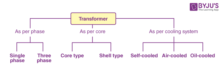
Transformer Types
Transformers are used in various fields like power generation grid, distribution sector, transmission and electric energy consumption. There are various types of transformers which are classified based on the following factors:
- Working voltage range
- The medium used in the core
- Winding arrangement
- Installation location
Based on Voltage Levels
Commonly used transformer types, depending on the voltage, are classified as follows:
- Step-up Transformer: They are used between the power generator and the power grid. The secondary output voltage is higher than the input voltage.
- Step-down Transformer: These transformers are used to convert high-voltage primary supply to low-voltage secondary output.
Based on the Medium of Core Used
In a transformer, we will find different types of cores that are used.
- Air Core Transformer: The flux linkage between primary and secondary winding is through the air. The coil or windings wound on the non-magnetic strip.
- Iron Core Transformer: Windings are wound on multiple iron plates stacked together, which provides a perfect linkage path to generate flux.
Based on the Winding Arrangement
- Autotransformer: It will have only one winding wound over a laminated core. The primary and secondary share the same coil. Auto means “self” in the Greek language.
Based on Install Location
- Power Transformer: It is used at power generation stations, as they are suitable for high voltage application
- Distribution Transformer: It is mostly used at distribution lanes for domestic purposes. They are designed for carrying low voltages. It is very easy to install and characterised by low magnetic losses.
- Measurement Transformers: They are mainly used for measuring voltage, current and power.
- Protection Transformers: They are used for component protection purposes. In circuits, some components must be protected from voltage fluctuation, etc. Protection transformers ensure component protection.
Working Principle of a Transformer
The transformer works on the principle of Faraday’s law of electromagnetic induction and mutual induction.
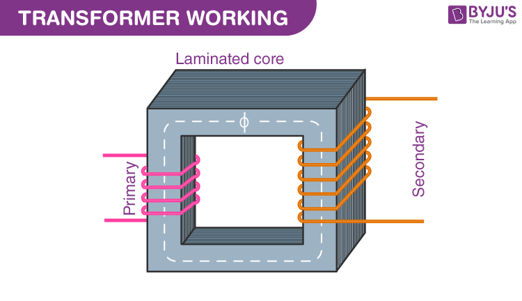
There are usually two coils – primary coil and secondary coil – on the transformer core. The core laminations are joined in the form of strips. The two coils have high mutual inductance. When an alternating current passes through the primary coil, it creates a varying magnetic flux. As per Faraday’s law of electromagnetic induction, this change in magnetic flux induces an EMF (electromotive force) in the secondary coil, which is linked to the core having a primary coil. This is mutual induction.
Overall, a transformer carries out the following operations:
- Transfer of electrical energy from one circuit to another
- Transfer of electrical power through electromagnetic induction
- Electric power transfer without any change in frequency
- Two circuits are linked with mutual induction
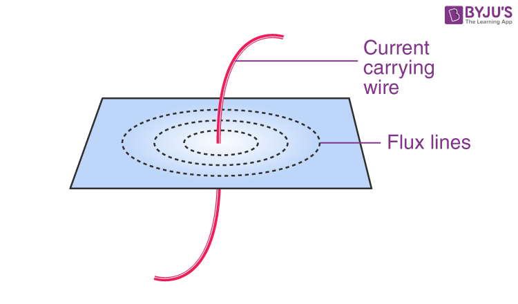
The figure shows the formation of magnetic flux lines around a current-carrying wire. The normal of the plane containing the flux lines is parallel to the normal of a cross-section of a wire.
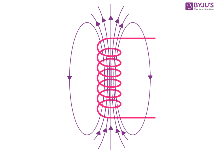
The figure shows the formation of varying magnetic flux lines around a wire wound. The interesting part is that the reverse is also true; when a magnetic flux line fluctuates around a piece of wire, a current will be induced in it. This was what Michael Faraday found in 1831, which is the fundamental working principle of electric generators, as well as transformers.
Parts of a Single-phase Transformer
The major parts of a single-phase transformer consist of
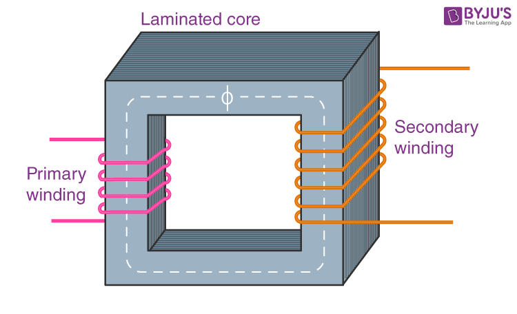
1. Core
The core acts as a support to the winding in the transformer. It also provides a low reluctance path to the flow of magnetic flux. The winding is wound on the core, as shown in the picture. It is made up of a laminated soft iron core in order to reduce the losses in a transformer. The factors, such as operating voltage, current, power, etc., decide core composition. The core diameter is directly proportional to copper losses and inversely proportional to iron losses.
2. Windings
Windings are the set of copper wires wound over the transformer core. Copper wires are used due to the following:
- The high conductivity of copper minimises the loss in a transformer because when the conductivity increases, resistance to current flow decreases.
- The high ductility of copper is the property of metals that allows it to be made into very thin wires.
-
There are mainly two types of windings: primary windings and secondary windings.
- Primary winding: The set of turns of windings to which the supply current is fed.
- Secondary winding: The set of turns of winding from which output is taken.
-
The primary and secondary windings are insulated from each other using insulation coating agents.
3. Insulation Agents
Insulation is necessary for transformers to separate windings from each other and to avoid short circuits. This facilitates mutual induction. Insulation agents have an influence on the durability and stability of a transformer.
The following are used as insulation mediums in a transformer:
-
-
-
- Insulating oil
- Insulating tape
- Insulating paper
- Wood-based lamination
-
-
Ideal Transformer
The ideal transformer has no losses. There is no magnetic leakage flux, ohmic resistance in its windings and no iron loss in the core.
EMF Equation of Transformer
N1 – Number of turns in the primary
N2 – Number of turns in the secondary
Φm – Maximum flux in the weber (Wb)
T – Time period. It is the time taken for 1 cycle.
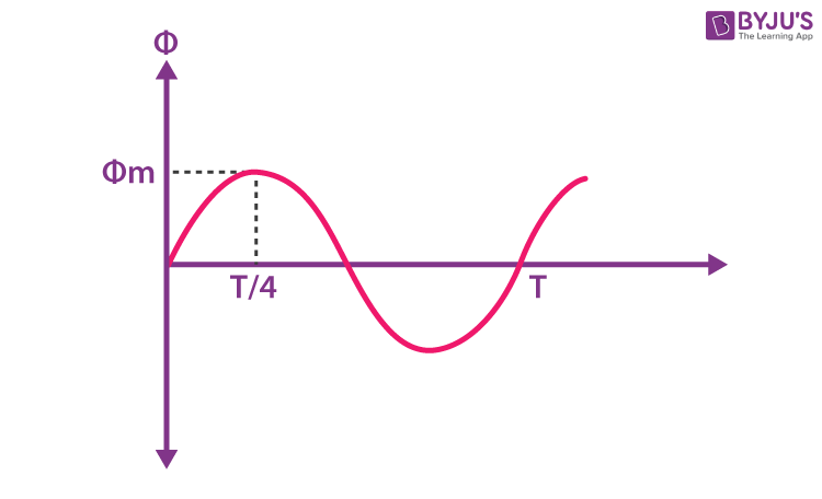
The flux formed is a sinusoidal wave. It rises to a maximum value of Φm and decreases to a negative maximum of Φm. So, flux reaches a maximum in one-quarter of a cycle. The time taken is equal to T/4.
Average rate of change of flux = Φm/(T/4) = 4fΦm
Where, f = frequency
T = 1/f
Induced EMF per turn = Rate of change of flux per turn
Form factor = RMS value / average value
RMS value = 1.11 (4fΦm) = 4.44 fΦm [form factor of a sine wave is 1.11]
RMS value of EMF induced in winding = RMS value of EMF per turn x No. of turns
Primary Winding
RMS value of induced EMF = E1 = 4.44 fΦm * N1
Secondary Winding
RMS value of induced EMF = E2 = 4.44 fΦm * N2
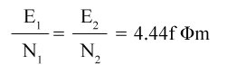
This is the EMF equation of the transformer.
For an ideal transformer at no load condition,
E1 = Supply voltage on the primary winding
E2 = Terminal voltage (theoretical or calculated) on the secondary winding
Voltage Transformation Ratio

K is called the voltage transformation ratio, which is a constant.
Case 1:If N2 > N1, K>1, it is called a step-up transformer.
Case 2: If N2< N1, K<1, it is called a step-down transformer.
Transformer Efficiency
Applications of Transformer
-
The transformer transmits electrical energy through wires over long distances.
-
Transformers with multiple secondaries are used in radio and TV receivers, which require several different voltages.
- Transformers are used as voltage regulators.
Transformer-related Solved Examples
1. A transformer has 600 turns of the primary winding and 20 turns of the secondary winding. Determine the secondary voltage if the secondary circuit is open and the primary voltage is 140 V.
Given
Total number of turns of the primary coil (N1) = 600 turns
Total number of turns of the secondary coil (N2) = 20 turns
Primary voltage (V1) = 140 V
Solution:
The voltage on the primary coil = N1V1
The voltage on the secondary coil = N2V2
The voltage on one turn
k is a transformation ratio.
V2 = 4.6 V
2. A transformer has a primary coil with 1600 loops and a secondary coil with 1000 loops. If the current in the primary coil is 6 Ampere, then what is the current in the secondary coil?
Given:
Primary coil (N1) = 1600 loops
Secondary coil (N2) = 1000 loops
The current in the primary coil (I1) = 4 A
Solution :
I2 = 6.4 A
The current on the secondary coil is 6.4 Ampere.
Frequently Asked Questions on Transformer
What is the working principle of the transformer?
The transformer works on the principle of mutual induction.
List the three types of transformers based on voltage level.
Based on the voltage level, the transformer is of three types, and they are as follows:
Step-up transformer
Step-down transformer
Isolation transformer
What are the main parts of a transformer?
Iron core
Primary winding
Secondary winding
When do transformers burn and explode?
Transformers burn and explode when lightning strikes, and during overloading, corrosion, power surges, etc.
What is a transformer?
A transformer is a device used for stepping up or stepping down AC voltages.
What is a step-up transformer?
A step-up transformer is one for which the output voltage is greater than the input voltage.
What is a step-down transformer?
A step-down transformer is one for which the output voltage is less than the input voltage.
Define the turns ratio of the transformer.
The turns ratio of a transformer is the ratio of the number of turns in the secondary to that of the primary.

Comments