In this lesson, we will explore the concepts of inductive reactance and capacitive reactance and understand all the underlying terms. Inductive reactance is usually related to the magnetic field surrounding a wire or a coil carrying current. Likewise, capacitive reactance is often linked with the electric field that keeps changing between two conducting plates or surfaces that are kept apart from each other by some insulating medium.
However, before we learn about these topics in detail, we will first recall the definition of reactance and then move on to understand its types. Inductive reactance and capacitive reactance are the two main types of reactance.
|
Table of Contents |
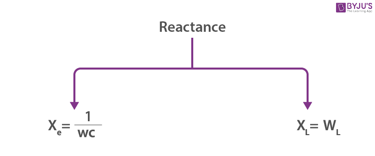
What Is Reactance?
Reactance is the opposition offered by the capacitor and inductor in a circuit to the flow of AC current in the circuit. It is quite similar to resistance, but reactance varies with the frequency of the ac voltage source. It is measured in ohms.
If we look at conductors that carry alternating current, we will find that reactance is always present along with resistance. Moreover, reactance also appears in shorter intervals, as the direct current changes while approaching or departing from a steady flow.

We will discuss them in detail below.
Inductive Reactance (XL)
Definition: Inductive reactance is the opposition offered by the inductor in an AC circuit to the flow of AC current.
It is represented by (XL) and measured in ohms (Ω). Inductive reactance is mostly low for lower frequencies and high for higher frequencies. It is, however, negligible for steady DC current.
The inductive reactance formula is given as follows:
Inductive Reactance, XL = 2πfL
The AC circuit with a pure inductor is represented as,

By KVL
and
XL = Lw = 2πLf (inductive reactance)
XL α L
XL α w → 1
Where
L – is the inductance of the coil
W – is the angular frequency of the AC voltage source.
From Equation 1,
W → Higher frequency → Higher resistance to the current flow
High (fhigh) (or)
Current changes more rapidly for higher frequencies
W = 0 → f = 0 → XL = 0
XL (Inductive reactance)
w ≠ 0 w = 0
XL = Lw XL = 0
for AC with fhigh → XL = High for DC XL → is zero
for AC with flow → XL = small XL = resistance of the wire in a circuit.
Since from phasor diagram for AC circuit with only resistor, capacitor and inductor.
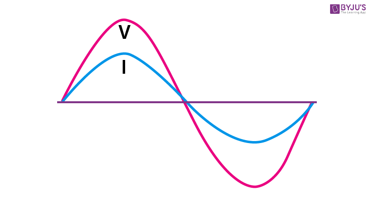
For an AC circuit with only a resistor and its phasor diagram:
AC circuit with only a resistor shows that current and voltage are in the same phase, which means an increase in voltage leads to an increase in current (vice-versa).

For an AC circuit with an only inductor (L):
We know that V = Vo sin wt
i = io cos wt
Current lags behind the voltage with a phase difference of π/2 between them.
AC circuit with R only
V = vo sin wt
i = io sin wt
AC circuit with L
V = vo sin wt
i = io sin wt
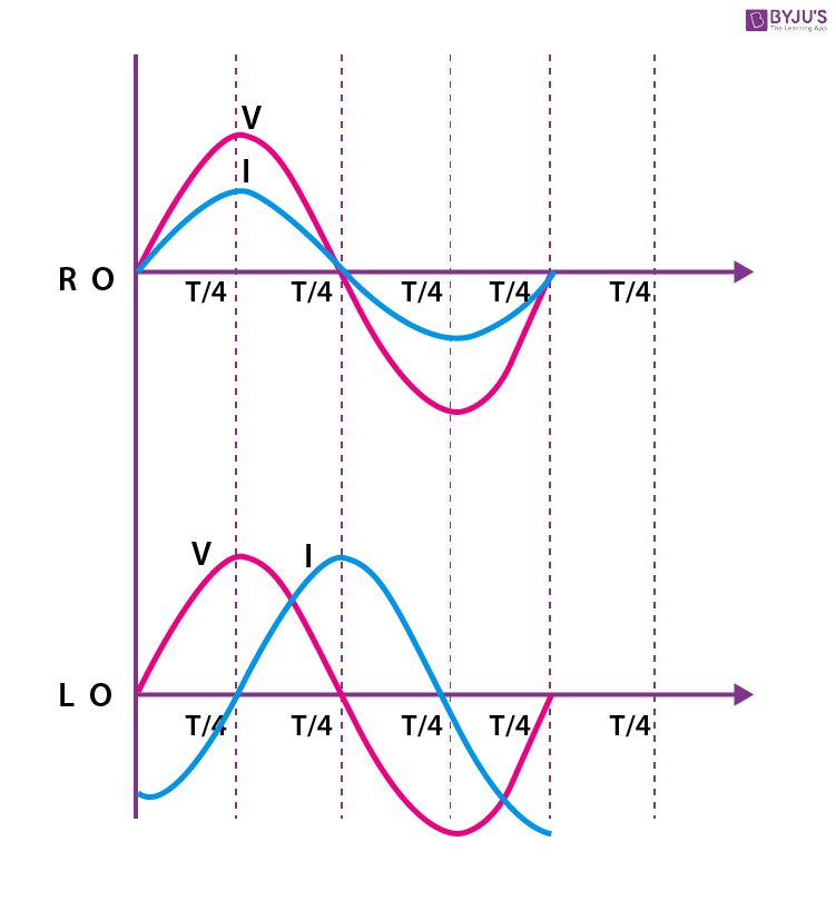
(i) As we can clearly see from the given phasor diagram above, in an AC circuit with a pure resistor, the AC current through it and the AC voltage across it rise together (or) fall together, which indicates both current and voltage are in phase.
(ii) But in the case of an AC circuit with L(only), it is clearly seen from the given phasor diagram that V and I are in out of phase. This means if V = max, then i = minimum.
(iii) This is because of the characteristics of the inductor. Inductance always opposes a change in current which means that current through an inductor continuously reverses itself.
(iv) Lenz’s Law: According to Lenz’s Law, a circuit with inductance offers opposing force to the change in current inducing counter emf (induced emf), maintaining the phase between v and I, which remains the same.
(v) We can see the above figure as four cycles.
(a) First (T/4) cycle
Applied Voltage starts increasing from zero.
When v = o, i = – Ve (max) = -imax
When v = Vmax,i = 0
(b) Second (T/4) cycle
Applied voltage starts decreasing from Vmax.
When V reaches:
V = o i = imax
(c) Third (T/4) cycle
The applied voltage starts increasing in the opposite direction (or) reverse direction.
When V reaches, V = – Vmax,
i starts decreasing reaches i = 0
(d) Fourth (T/4) cycle
The applied voltage starts decreasing from – Vmax to zero, but i reaches the –imax.
V = 0 , i = – imax
Inertia Effect by Inductor
We can see from the above analysis that V and i are continuously changing in magnitude and direction. This is because the inductor continuously reverses the current through it by itself due to the inertia effect of emf.
Inertia effect for > inertia effect for DC
Similarly, for AC,
Greater the value of (L) inductance → greater the opposition by inertia effect
Faster the reversal of current → greater the opposition by inertia effect.
For the opposition that is offered by the inductor to the flow of an alternating current, we cannot call it resistance because this is not friction within the conductor; this is the reaction of the inductor to the change in alternating current.
Special Cases
An inductor (L) → has appreciable XL for AC source and reduces the amount of current.
Case (I): Inductor and a bulb in series with an AC source

(i) Circuit without inductor (ii) circuit with a high inductor (iii) circuit with low inductor
There is no inductor, XL = 1000Ω for DC inductor offers
AC source causes the bulb glows
With full bright = 0.012 A i = 1.4 A
Case (II): Combination of inductive reactance
XL = provides opposition to an AC source. So, it is summed in the same way as resistance.
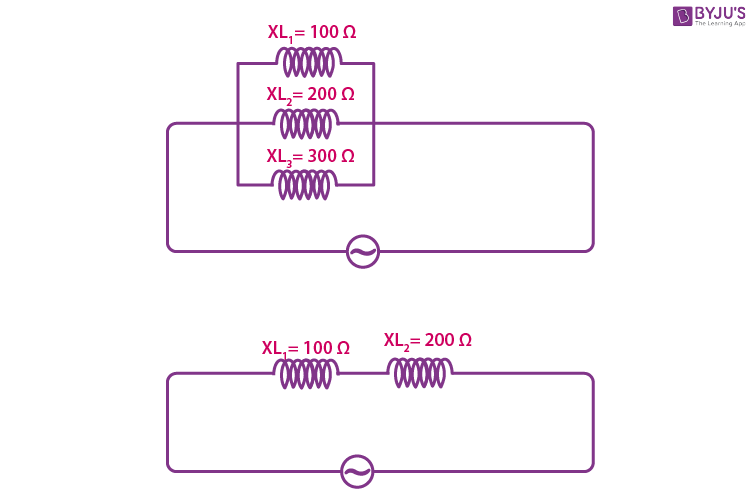
XLeft = XL1 + XL2
Case (III): Current in AC circuit with inductors only


= I × L1+IXL2
= I(X L1+XL2)
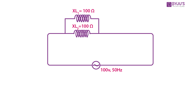
I = 1/2 A
Application of Inductive Reactance
XL – for AC offers minimum reactance to AC at low frequency and maximum reactance to AC at high frequency.
Solved Problems
Problem 1: Find out the XL for an AC source of 100 v and 50 Hz by an inductor L = 50 mπ.
XL = Lw = 50 × 10–3 × 2π × 50 = 5000π × 10–3 = 5π
Problem: 2 An inductor offers a resistance of 100 Ω to an AC source of 100 v and 50 Hz. Find out the value of the inductor.
XL = LW
Difference between Resistance and Reactance
Resistance → is frequency-independent
Reactance → is frequency-dependent.
- An inductor is connected to an AC source of 100 v and 50 Hr. What happens to the current in the circuit if the frequency increases?
XL = Lw, for increase in(f), cause increase in XL
- An inductor is connected to an AC source of 100 V and 50 Hr. What happens to the current in the circuit if its frequency decreases?
XL = Lw, for decreases in (f), causes decrease in XL
Capacitive Reactance
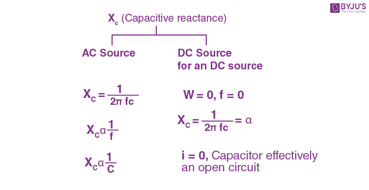
What is capacitive reactance? The definition of capacitive reactance states that it is the opposition offered by a capacitor to the flow of AC current in the AC circuit. A capacitor opposes the changes in the potential difference or the voltage across its plates. Capacitive reactance is said to be inversely proportional to the capacitance and the signal frequency. It is normally represented by (Xc) and measured in the SI unit of ohm (Ω).
The capacitive reactance formula is given as follows:
Capacitive reactance, Xc = 1/2fC
The AC circuit with a pure capacitor is represented as,
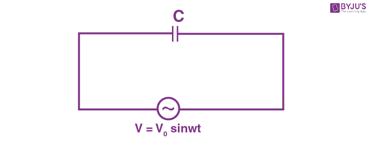
According to KVL,
CVo sin wt = q
wcvo cos twt = i
where wcVo = io
AC current flows through the capacitor when AC voltage is applied.
If c – is small → allows small the current
F – is small → smaller the current
Since,
V = Vo sinwt
i = io coswt = io sin
Current (i) leads with the phase difference π/2 to the applied voltage.
As we know, there is no current through the dielectrics of the capacitor, but alternative charging/discharging of the capacitor appears as the current passing through the capacitor.
When an AC voltage is applied → Alternative charging and discharging happen to the capacitor continuously, and it appears as the current passing through the capacitor.
AC circuit with a pure resistor
V = vo sin wt
i = io sin wt
AC circuit with a pure capacitor
v = vo sin wt
I – io cos wt
The figure above shows the phasor diagram of the AC circuit with a pure resistor and pure capacitor. We can clearly see the difference between the phasor diagram of a pure resistor and a pure inductor.
Now, we will discuss the phasor diagram of the pure capacitor:
From t = 0 to t = T/4, an AC voltage is increasing in positive change in the AC voltage at its greatest rate, as we know that the charge on the capacitor varies directly proportional to the applied voltage. So, it tells that the charge on the capacitor is also changing at its greatest rate. In other words, a greater number of electrons are moving off from one plate to another plate.
When V = Vmax, I = o, which means the capacitor reached a steady state (fully charged).
When voltage approaches maximum, the change in AC voltage approaches zero (becomes less), and the current must decrease to zero.
The second cycle of (T/4):
V = Vmax to V = approaches to zero.
V is decreasing, but still, in positive, it means the plates which have accumulated with an excess amount of electrons must lose some electrons, and the current flow must reverse its direction of the current, which is increasing in –ve.
The third cycle of (T/4):
Voltage from Vo to V = – Vmax
Applied AC voltage polarity is reversed; it starts increasing to Vmax in –ve direction when v reaches Vmax, which means charges are equally distributed between the plates of the capacitor. At Vmax – the capacitor reaches a steady state (fully charged), so i reaches i = 0 (zero).
Similarly, the fourth cycle of (T/4):
Again voltage starts decreasing from Vc = Vmax to V = Vo, the capacitor must lose some charges from its negative plates by discharging.
The above-discussed four cycles repeat further and further.
Done to the charging/discharging process:
The amplitude and polarity of the AC voltage and amplitude and direction of AC current are continuously charging.
The direction and strength of the current are in relation to the polarity and strength of voltage that appears across the plates of the capacitor, which changes the direction of charge flow at the same rate as AC applied voltage. This makes the capacitor to pass an AC current. Actually, charges do not pass through the dielectric, but the rushing effect involving back and forth motion of charges from plate to plate causes opposition to arise during the flow of charge.
That opposition is (Xc).
For a given AC voltage with a frequency number of charges which can go back and forth between plates of the capacitor is limited by the storage capacity of the capacitor, which is called capacitance of capacitor, and the opposition offered by the capacitor is called capacitive reactance (Xc).
Special Cases
Capacitor offers opposition to the AC current through the circuit (Xc).
Case (I):

There is no current through the dielectrics of the capacitor.
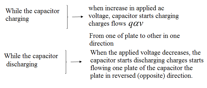
By increasing the applied voltage: Capacitor starts charging and starts to flow from one place to another in one direction.
When the applied voltage is decreased: The capacitor starts discharging. Now, the direction of charge transfer is reversed.
Capacitor alternatively charges and discharges}→ When an AC voltage is given to it.
Capacitor reactance with AC and DC:
![]()
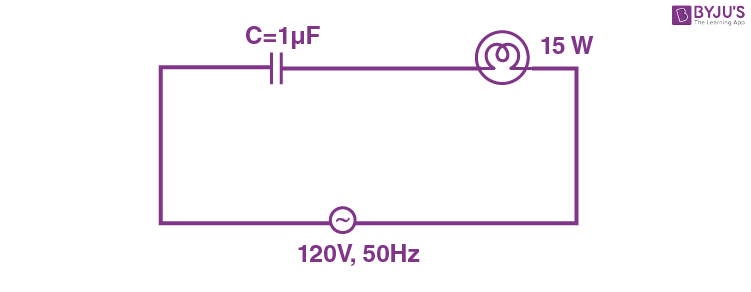
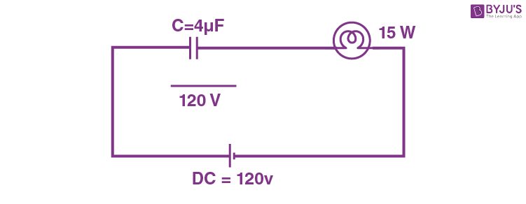
A 4μf capacitor is connected in, and for this case, the bulb glows less for DC w = 0
Series to the bulb, the bulb glows bright, then 4μF capacitor for DC capacitor applies ∞
When it is shining brightly, we get i = Vo / Xc = Vo WC resistance whole of potential i α c is dropped across the capacity, so the bulb cannot light up.
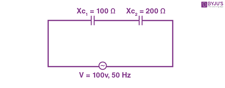
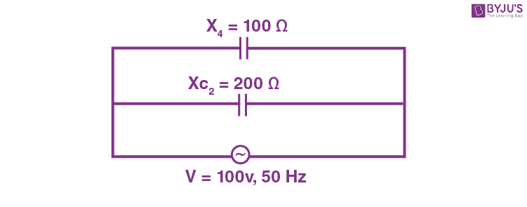
Case (II): Series and parallel capacitive reactance
Xc – Capacitive reactance is nothing in opposition to the AC current. They behave as resistors, and they will be assumed the same as resistors connected in series and parallel.
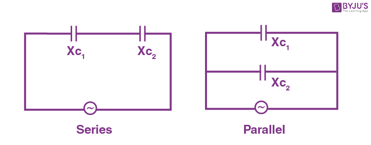
Xc1 = Xc1 + Xc2 + …
Case (III): Current through capacitive reactance
Application of capacitive reactance
Xc – Blocks the DC current
Xc – Offers low reactance to AC
Solved Problems
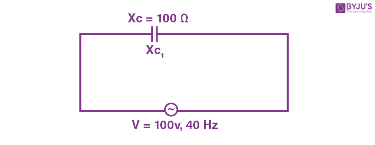
Problem 1: Find out the capacitive reactance (Xc) for an AC source of 100 v and 50 Hz by a capacitor of c = 20 μF.
Solution:
Problem 2: A capacitor offers a resistance of 100 Ω to an AC source of 100 v and 50 Hw. Find out the value of the capacitor. C = ?
Solution:
Common Questions
1. What happens to the XC as the frequency of an AC source decreases?
F – decreases, Xc – increases
2. What happens to the XC as the frequency of an AC source increases?
Increases in f 🡪cause Xc to decrease
3. What happens to the Xc for smaller capacitors?
Frequently Asked Questions on Inductive Reactance and Capacitive Reactance
What is the ratio of inductive reactance and capacitive reactance in an AC circuit?
The ratio of inductive reactance and capacitive reactance in an AC circuit is
ω2LC
Where,
L is the inductance.
C is the capacitance.
ω is the angular frequency.
What is the expression for inductive reactance?
Inductive reactance, XL = Lω
Where,
L is the inductance.
ω is the angular frequency.
What is the expression for capacitive reactance?
Capacitive reactance, XC = 1/Cω
Where,
C is the capacitance.
ω is the angular frequency.

Put your understanding of this concept to test by answering a few MCQs. Click ‘Start Quiz’ to begin!
Select the correct answer and click on the “Finish” button
Check your score and answers at the end of the quiz
Visit BYJU’S for all JEE related queries and study materials
Your result is as below
Comments