What Is a Capacitor?
A capacitor is a device in which electrical energy can be stored. It is an arrangement of two conductors, generally carrying charges of equal magnitudes and opposite signs, and separated by an insulating medium. The non-conductive region can either be an electric insulator or vacuum, such as glass, paper or air, or a semi-conductor called a dielectric.
Capacitors vary in shape and size, and they have many important applications in electronics.
Related Physics Concepts:
- Capacitor, Types and Capacitance
- Combination of Capacitors
- Energy Stored in a Capacitor
What Are Capacitors Used for?
- Storing electric potential energy such as batteries.
- Filtering out unwanted frequency signals
- Delaying voltage changes when coupled with resistors.
- Used as a sensing device.
- Used in the audio system of the vehicle.
- Used to separate AC and DC.
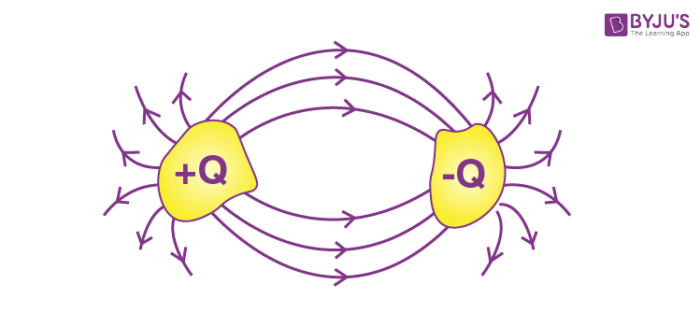
One of the conductors has a positive charge of +Q, and it is at potential +V, whereas the other has an equal negative charge -Q and is at potential -V.
Charge on Capacitor
Note: The charge on the capacitor is Q.
The total charge/the net charge on the capacitor is –Q + Q = 0.
Circuit Symbols

Charge Distribution between Capacitors – Video Lesson

Capacitance
The charge on the capacitor (Q) is directly proportional to the potential difference (V) between the plates, i.e.,
The constant of proportionality (C) is termed as the capacitance of the capacitor.
Dimensional Formula and Unit of Capacitance
- Unit of Capacitance: Farad (F)
The capacitor value can vary from a fraction of a picofarad to more than a microfarad. Voltage levels can range from a couple to a substantial couple of hundred thousand volts.
- Dimensional Formula: M-1L-2I2T4
Commonly Used Scales
- \(\begin{array}{l}\mu F\end{array} \)= 10-6F
- nF = 10-9F
- pF = 10+2F
Factors Affecting Capacitance
Capacitance depends on the following factors:
- Shape and size of the conductor
- Medium between them
- Presence of other conductors near it
Calculation of Capacitance
We will try to calculate the capacitance of differently shaped capacitors, and the steps are as follows:
- Assume the charge on the conductors (Q)
- Calculate the electric field between the plates (E)
- Calculate the potential difference from the electric field (V)
- Apply the relation, \(\begin{array}{l}C=\frac{Q}{V}\end{array} \)
Types of Capacitors
- Parallel Plate Capacitor
- Spherical Capacitor
- Cylindrical Capacitor
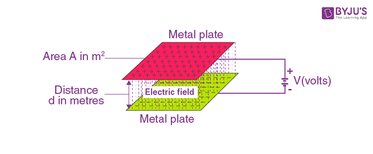
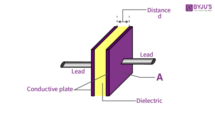
Parallel Plate Capacitor
The parallel plate capacitor consists of two metal plates of area A, and is separated by a distance d. The plate on the top is given a charge +Q, and that at the bottom is given the charge –Q. A potential difference of V is developed between the plates.
The separation is very small compared to the dimensions of the plate, so the effect of bending outward of electric field lines at the edges and the non-uniformity of surface charge density at the edges can be ignored.
The charge density on each plate of the parallel plate capacitor has a magnitude of σ.
σ = Q/A
From Gauss’s law, E = Q/ε0A
Also, E = V/d
Now, taking field due to the surface charges outside the capacitor,
This result is valid for the vacuum between the capacitor plates. For other media, then capacitance will be
If there is a vacuum between the plates, k = 1.
Parallel Plate Capacitor – Video Lesson

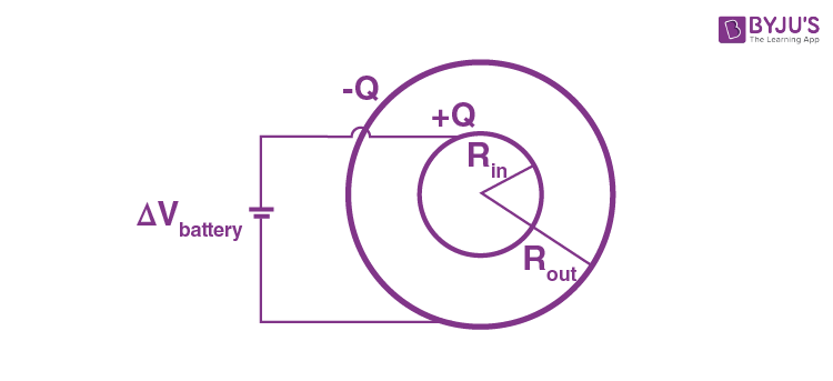
Spherical Capacitor
Let’s consider a spherical capacitor that consists of two concentric spherical shells. Suppose the radius of the inner sphere, Rin = a and the radius of the outer sphere, Rout = b. The inner shell is given a positive charge +Q, and the outer shell is given –Q.
The potential difference,
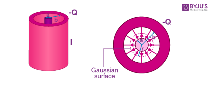
Cylindrical Capacitor
Consider a solid cylinder of radius a surrounded by a cylindrical shell, b. The length of the cylinder is l and is much larger than a-b to avoid edge effects. The capacitor is charged so that the charge on the inner cylinder is +Q and the outer cylinder is –Q.
From Gauss’s law,
Where λ = Q/l, linear charge density
The potential difference of cylindrical capacitor is given by,
Where, we have chosen the integration path to be along the direction of the electric field lines. As expected, the outer conductor with a negative charge has a lower potential, which gives
Once again, we see that the capacitance C depends only on the geometrical L, a and b.
Cylindrical Capacitor

Problems on Capacitor and Capacitance
Problem 1: Find the capacitance of a conducting sphere of radius R.
Sol: Let charge Q is given to sphere. The field outside the sphere at distance r is:
Problem 2: A parallel plate air capacitor is made using two plates 0.2 m square, spaced 1 cm apart. It is connected to a 50 V battery.
- What is the capacitance?
- What is the charge on each plate?
- What is the electric field between two plates?
- If the battery is disconnected and then the plates are pulled apart to a separation of 2 cm, what are the answers to the above parts?
Sol:
- \(\begin{array}{l}C_{0} = \frac{\varepsilon_{0}A}{d_{0}} = \frac{8.85\times10^{-12}\times0.2\times0.2}{0.01}\end{array} \)= 35.4 x 10⁻¹² F
- \(\begin{array}{l}Q_0=C_{0}V_{0}=(35.4\times 10^{-12}\times50)C = 1.77\times10^{-5}C = 1770 \times 10^{-12}C\end{array} \)
- \(\begin{array}{l}E_{0} = \frac{V_{0}}{d_{0}} =\frac{50}{0.01} = 5000V/m\end{array} \)
- If the battery is disconnected, the charge on the capacitor plates remains constant, while the potential difference between plates can change.
Problem 3: A parallel plate conductor connected in the battery with a plate area of 3.0 cm2 and plate separation of 3 mm if the charge stored on the plate is 4.0pc. Calculate the voltage of the battery.
Sol:
Area A = 3.0 cm2 = 3.0 × 10⁻⁴ m2
Ca = 8.85 × 10⁻¹³
V = 4.52 V
Dielectrics and Capacitance
What Are Dielectrics?
It is an insulating material (non-conducting) which has no free electrons. But a microscopic displacement of charges is observed in the presence of an electric field. It is found that the capacitance increases as the space between the conducting plates is filled with dielectrics.
Polar and Non-polar Dielectrics
Each atom is made of a positively charged nucleus surrounded by electrons. If the centre of the negatively charged electrons does not coincide with the centre of the nucleus, then a permanent dipole (separation of charges over a distance) moment is formed. Such molecules are called polar molecules. If a polar dielectric is placed in an electric field, the individual dipoles experience a torque and try to align along the field.
In non-polar molecules, the centres of the positive and negative charge distributions coincide. There is no permanent dipole moment created. But in the presence of an electric field, the centres are slightly displaced. This is called induced dipole moments.

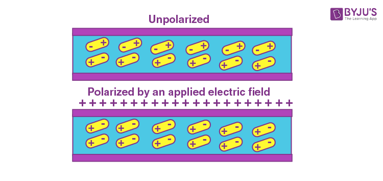
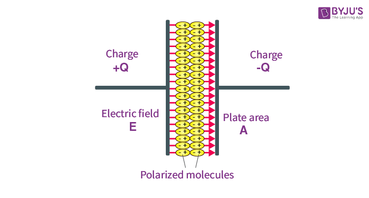
Polarization of a Dielectric Slab
It is the process of inducing charges on the dielectric and creating a dipole moment. Dipole moment appears in any volume of a dielectric.
Dielectric Constant
The induced electric field is opposite in direction to the applied field. But the resultant field is in the direction of the applied field with reduced magnitude.
Effect of Dielectric on Capacitance
Dielectric Slabs in Series
A parallel plate capacitor contains two dielectric slabs of thickness d1, d2 and dielectric constant k1 and k2, respectively. The area of the capacitor plates and slabs is equal to A.
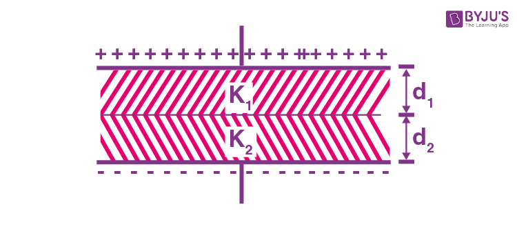
Considering the capacitor as a combination of two capacitors in series, the equivalent capacitance C is given by:
Dielectric Slabs in Parallel
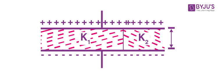
Consider a capacitor with two dielectric slabs of the same thickness d placed inside it, as shown in the figure. The slabs have dielectric constants k1 and k2 and areas A1 and A2, respectively. Treating the combination as two capacitors in parallel,
C = C1 + C2
Dielectric and Vacuum
If there exists a dielectric slab of thickness t inside a capacitor whose plates are separated by distance d, the equivalent capacitance is given as:
The equivalent capacitance is not affected by changing the distance of the slab from the parallel plates. If the slab is of metal, the equivalent capacitance is:
Problems on Capacitance and Dielectrics
Problem 1: Three capacitors of 10μF each are connected, as shown in the figure. Two of them are now filled with dielectric with K = 2, and K = 2.5. Find the equivalent capacitance.
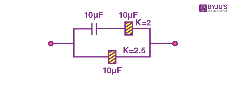
After the insertion of dielectrics,
C1 = 10μF; C2 = KC0 = 2 x 10 = 20μF; C3 = KC0 = 2.5 x 10 = 25 μF
Problem 2: Find the equivalent capacitance of the system shown in the figure (assume square plates).
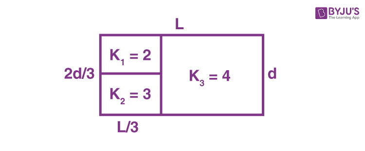
Taking K1 = 2 to be series in K2 = 3
Now, Cleft and Cright are in parallel.
Problem 3: Calculate the effective capacitance connected in series and parallel. The capacitors are connected to a 40 V battery. Also, calculate the voltage across the capacitors for each connection type.
Given
C1 = 12 F
C2 = 6 F
Solu:
When capacitors are connected in series,
C = 4 F
Q = CV
Q = 4 × 40
Q = 160 C
For the 12 F capacitor:
V = 13.33V
For the 6F capacitor:
V = 26.66V
When capacitors are connected in parallel,
C = C1 + C2
C = 12 + 6
C = 18 F
The voltage is the same as 40V across each capacitor.
You might also be interested in the following:
Capacitor and Its Capacitance, Types of Capacitors

Combination of Charged Capacitor & Circuit Theory
Charging of a Capacitor – Electrostatic Potential and Capacitance
Watch this Video for More Reference

Electrostatics and Capacitor – Important Topics

Electrostatics and Capacitor – Important Questions

Frequently Asked Questions on Types of Capacitors and Capacitance
Define the capacitance of a capacitor.
The capacitance of a capacitor is the ratio of the magnitude of the charge on either conductor or the potential difference between the conductors forming the capacitor.
How can the capacitance of the parallel plate capacitor be increased?
The capacitance of the parallel plate capacitor can be increased in the following ways:
Increasing the area of the plates.
Decreasing the distance between the plates.
Using a medium of higher dielectric constant.
Does the capacitance of the capacitor change when the charge on it is doubled?
The capacitance is independent of charge, therefore, it remains the same.
What happens to the charge on the parallel plate capacitor when the potential difference between the plates is doubled?
The charge also gets doubled.

Comments