Kirchhoff’s circuit laws lie at the heart of circuit analysis. With the help of these laws and the equation for individual components (resistor, capacitor and inductor), we have the basic tool to start analyzing circuits. In this article, we will discuss Kirchhoff’s current and voltage law and how to employ them in circuit analysis.
| Table of Contents: |


History about Gustav Robert Kirchhoff

Gustav Robert Kirchhoff, a German physicist, was born on March 12, 1824, in Konigsberg, Prussia. His first research topic was the conduction of electricity. This research led to Kirchhoff formulating the Laws of Closed Electric Circuits in 1845. These laws were eventually named after Kirchhoff and are now known as Kirchhoff’s Voltage and Current Laws. Since these laws apply to all electric circuits, understanding their fundamentals is paramount in understanding how an electronic circuit functions. Although these laws have immortalised Kirchhoff in Electrical Engineering, he has additional discoveries. He was the first person to verify that an electrical impulse travelled at the speed of light. Furthermore, Kirchhoff made a major contribution to the study of spectroscopy, and he advanced the research into blackbody radiation.
Read More: Absorption Spectrum
What Are Kirchhoff’s Laws?
In 1845, a German physicist, Gustav Kirchhoff, developed a pair of laws that deal with the conservation of current and energy within electrical circuits. These two laws are commonly known as Kirchhoff’s Voltage and Current Law. These laws help calculate the electrical resistance of a complex network or impedance in the case of AC and the current flow in different network streams. In the next section, let us look at what these laws state.

- Kirchhoff’s Current Law goes by several names: Kirchhoff’s First Law and Kirchhoff’s Junction Rule. According to the Junction rule, the total of the currents in a junction is equal to the sum of currents outside the junction in a circuit.
- Kirchhoff’s Voltage Law goes by several names: Kirchhoff’s Second Law and Kirchhoff’s Loop Rule. According to the loop rule, the sum of the voltages around the closed loop is equal to null.
Kirchhoff’s First Law or Kirchhoff’s Current Law
According to Kirchhoff’s Current Law,
The total current entering a junction or a node is equal to the charge leaving the node as no charge is lost.
Put differently, the algebraic sum of every current entering and leaving the node has to be null. This property of Kirchhoff law is commonly called conservation of charge, wherein I(exit) + I(enter) = 0.
Read More: Kirchhoff’s First Law
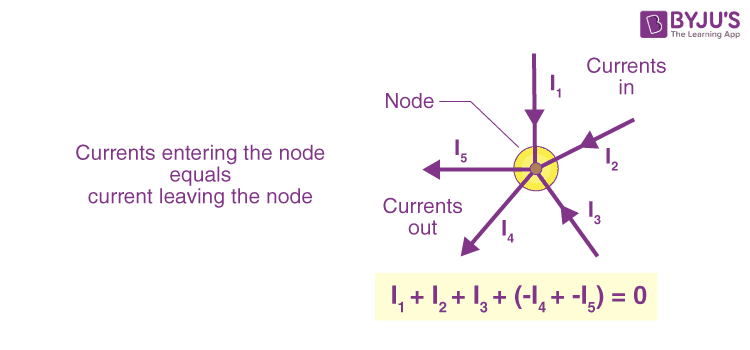
In the above figure, the currents I1, I2 and I3 entering the node is considered positive, likewise, the currents I4 and I5 exiting the nodes is considered negative in values. This can be expressed in the form of an equation:
I1 + I2 + I3 – I4 – I5 = 0
A node refers to a junction connecting two or more current-carrying routes like cables and other components. Kirchhoff’s current law can also be applied to analyse parallel circuits.
Kirchhoff’s Second Law or Kirchhoff’s Voltage Law
According to Kirchhoff’s Voltage Law,
The voltage around a loop equals the sum of every voltage drop in the same loop for any closed network and equals zero.
Put differently, the algebraic sum of every voltage in the loop has to be equal to zero and this property of Kirchhoff’s law is called conservation of energy.
Read More: Kirchhoff’s Second Law

When you begin at any point of the loop and continue in the same direction, note the voltage drops in all the negative or positive directions and returns to the same point. It is essential to maintain the direction either counterclockwise or clockwise; otherwise, the final voltage value will not be zero. The voltage law can also be applied in analyzing circuits in series.
When either AC circuits or DC circuits are analysed based on Kirchhoff’s circuit laws, you need to be clear with all the terminologies and definitions that describe the circuit components like paths, nodes, meshes, and loops.
Kirchhoff’s Law Solved Example
If R1 = 2Ω, R2 = 4Ω, R3 = 6Ω, determine the electric current that flows in the circuit below.

Solution:
-
- Following are the things that you should keep in mind while approaching the problem:
-
- You need to choose the direction of the current. In this problem, let us choose the clockwise direction.
- When the current flows across the resistor, there is a potential decrease. Hence, V = IR is signed negative.
- If the current moves from low to high, then the emf (E) source is signed positive because of the energy charging at the emf source. Likewise, if the current moves from high to low voltage (+ to -), then the source of emf (E) is signed negative because of the emptying of energy at the emf source.
In this solution, the direction of the current is the same as the direction of clockwise rotation.
– IR1 + E1 – IR2 – IR3 – E2 = 0
Substituting the values in the equation, we get
–2I + 10 – 4I – 6I – 5 = 0
-12I + 5 = 0
I = -5/-12
I = 0.416 AThe electric current that flows in the circuit is 0.416 A. The electric current is signed positive which means that the direction of the electric current is the same as the direction of clockwise rotation. If the electric current is negative then the direction of the current would be in anti-clockwise direction.
-
Watch the video and practise more numericals on Kirchhoff’s Law
| Related Links |
Frequently Asked Questions – FAQs
State Kirchhoff’s Current Law
Kirchhoff’s Current Law states that the total current entering a junction or a node equals the charge leaving the node as no charge is lost.
What is Kirchhoff’s First Law also known as?
Kirchhoff’s First Law is also known as Kirchhoff’s Current Law.
State Kirchhoff’s voltage law
Kirchhoff’s voltage law states that the voltage around a loop equals the sum of every voltage drop in the same loop for any closed network and equals zero.
Who put forth Kirchhoff’s laws?
Kirchhoff’s second law is also known as?
Kirchhoff’s second law is also known as Kirchhoff’s voltage law.
Watch the video and learn basic electrical circuit concepts and learn to solve problems on Electrical Circuit, KCL, and KVL.

Stay tuned to BYJU’S and Fall in Love with Learning!

Put your understanding of this concept to test by answering a few MCQs. Click ‘Start Quiz’ to begin!
Select the correct answer and click on the “Finish” button
Check your score and answers at the end of the quiz
Visit BYJU’S for all Physics related queries and study materials
Your result is as below
#nice explanation
😊😊😊😊😊😊Helpful.
good explanation
Nice explanation
Thanks
thanks a lot for keeping it nice and short. I hope the best for you man.
Helped a lot
Thank you .
Thanks for this!!!
Well explained. i appreciate it.
Thanks
This explanation is better than the one in the text book
Thank you byjus for this wonderful explanation
Very Helpful
Thanks, BYJU’S Team
I like this app
Very helpful
explains very well