Introduction To Young’s Double Slits Experiment
During the year 1801, Thomas Young carried out an experiment where the wave and particle nature of light and matter were demonstrated. The schematic diagram of the experimental setup is shown below-


A beam of monochromatic light is made incident on the first screen, which contains the slit S0. The emerging light then incident on the second screen which consists of two slits namely, S1, S2. These two slits serve as a source of coherent light. The emerging light waves from these slits interfere to produce an interference pattern on the screen. The interference pattern consists of consecutive bright and dark fringes. The dark fringes are the result of destructive interference and bright fringes are the result of constructive interference.
You may also want to check out these topics given below!


- The light falls on the screen at the point P. which is at a distance y from the centre O.
- The distance between the double-slit system and the screen is L
- The two slits are separated by the distance d
- Distance travelled by the light ray from slit 1 to point P on the screen is r1
- Distance travelled by the light ray from slit 2 to point P on the screen is r2
- Thus, the light ray from slit 2 travels an extra distance of ẟ = r2-r1 than light ray from slit 1.
- This extra distance is termed as Path difference.
Refer to Figure(3) Applying laws of cosines; we can write –
∵ Cos(90° – θ) = Sinθ
Similarly,
∵ Cos(90° + θ) = -Sinθ
Subtracting equation (2) from (1) we get-
Let us impose the limit that the distance between the double slit system and the screen is much greater than the distance between the slits. That is L >> d. The sum of r1 and r2 can be approximated to r1 + r2 ≅2r. Thus, the path difference becomes –
In this limit, the two rays r1 and r2 are essentially treated as parallel. (See Figure(4))

Figure(4): Assuming L >> d, The path difference between two rays.
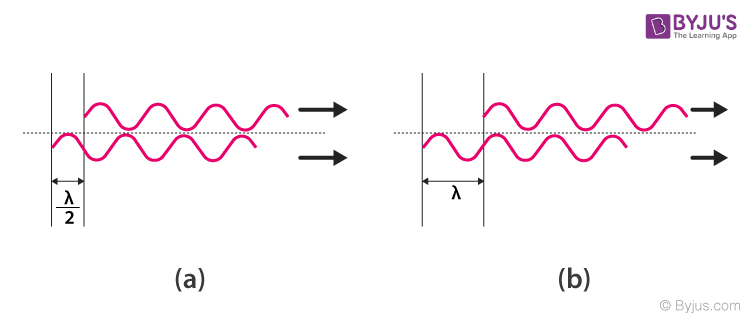
To compare the phase of two waves, the value of path difference (ẟ) plays a crucial role.
Constructive interference is seen when path difference (𝛿) is zero or integral multiple of the wavelength (λ).
| (Constructive interference) 𝛿 = dSin𝜃 = mλ —-(5), m = 0, ±1, ±2, ±3, ±4, ±5, …… |
Where m is order number. The Zeroth order maximum (m=0)corresponds to the central bright fringe, here 𝜃=0. The first order maxima(m=±1)(bright fringe) are on either side the central fringe.
Similarly, when 𝛿 is an odd integral multiple of λ/2, the resultant fringes will be 1800 out of phase, thus, forming a dark fringe.
| (Destructive interference) 𝛿 = dSin𝜃 = \(\begin{array}{l}\left [ m+\frac{1}{2} \right ]\end{array} \) λ—(6), m = 0, ±1, ±2, ±3, ±4, ±5, …… |
Assuming the distance between the slits are much greater than the wavelength of the incident light, we get-
Substituting it in the constructive and destructive interference condition we can get the position of bright and dark fringes, respectively. The equation is as follows-
\(\begin{array}{l}y_{b}=m\frac{\lambda L}{d}\end{array} \) |
And
\(\begin{array}{l}y_{d}=\left [ m+\frac{1}{2} \right ]\frac{\lambda L}{d}\end{array} \) |

loads of thanks for providing these free study materials
will help students a lot