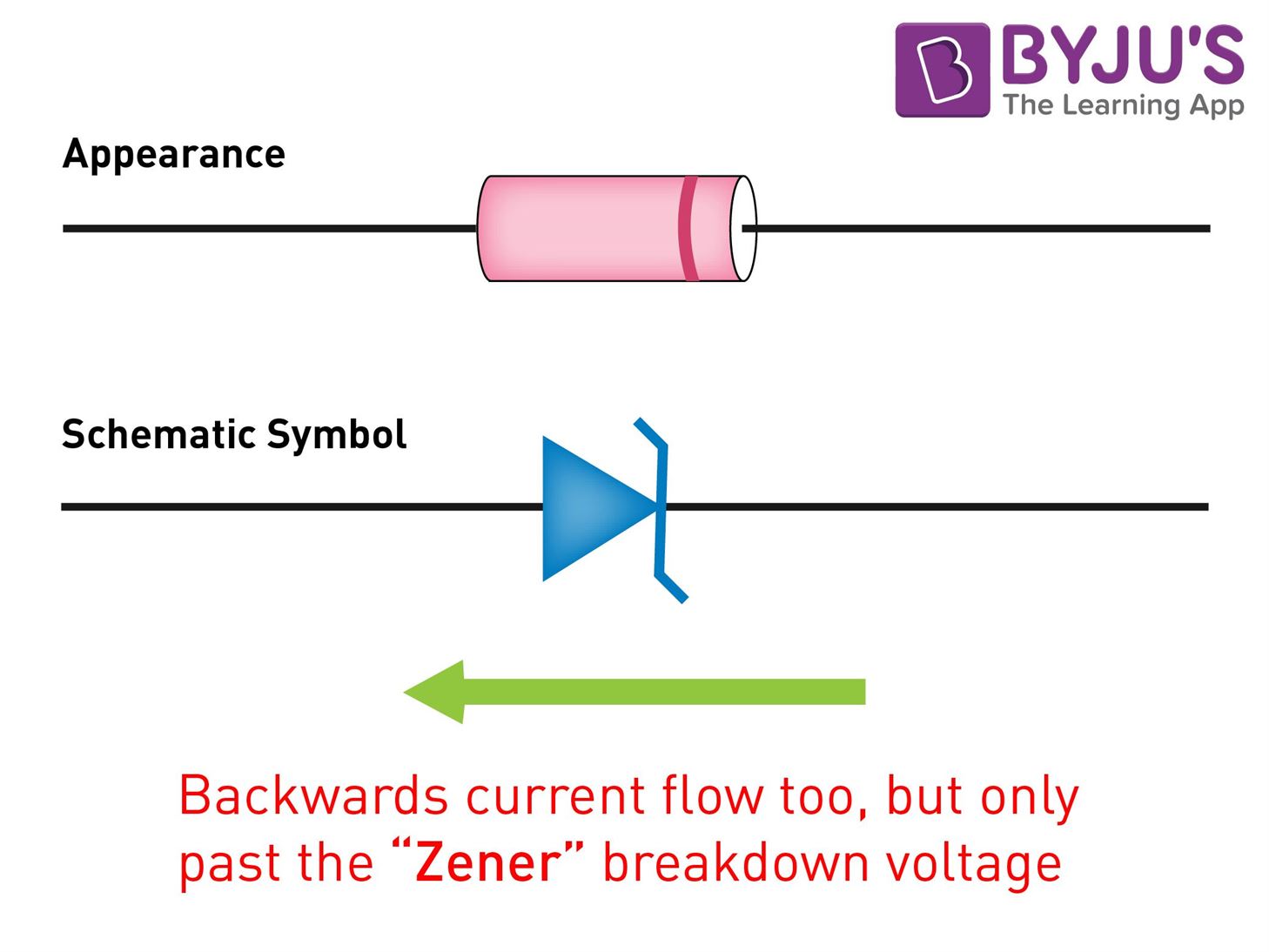
Zener diode is a silicon semiconductor with a p-n junction that is specifically designed to work in the reverse biased condition. When forward biased, it behaves like a normal signal diode, but when the reverse voltage is applied to it, the voltage remains constant for a wide range of currents. Due to this feature, it is used as a voltage regulator in d.c. circuit. The primary objective of the Zener diode as a voltage regulator is to maintain a constant voltage. Let us say if Zener voltage of 5 V is used then, the voltage becomes constant at 5 V, and it does not change.
| Table of Contents: |
What is a Voltage Regulator?

A voltage regulator is a device that regulates the voltage level. It essentially steps down the input voltage to the desired level and keeps it at that same level during the supply. This ensures that even when a load is applied the voltage doesn’t drop. The voltage regulator is used for two main reasons, and they are:
- To vary or regulate the output voltage
- To keep the output voltage constant at the desired value in spite of variations in the supply voltage.
Voltage regulators are used in computers, power generators, alternators to control the output of the plant.
Zener Diode as a Voltage Regulator
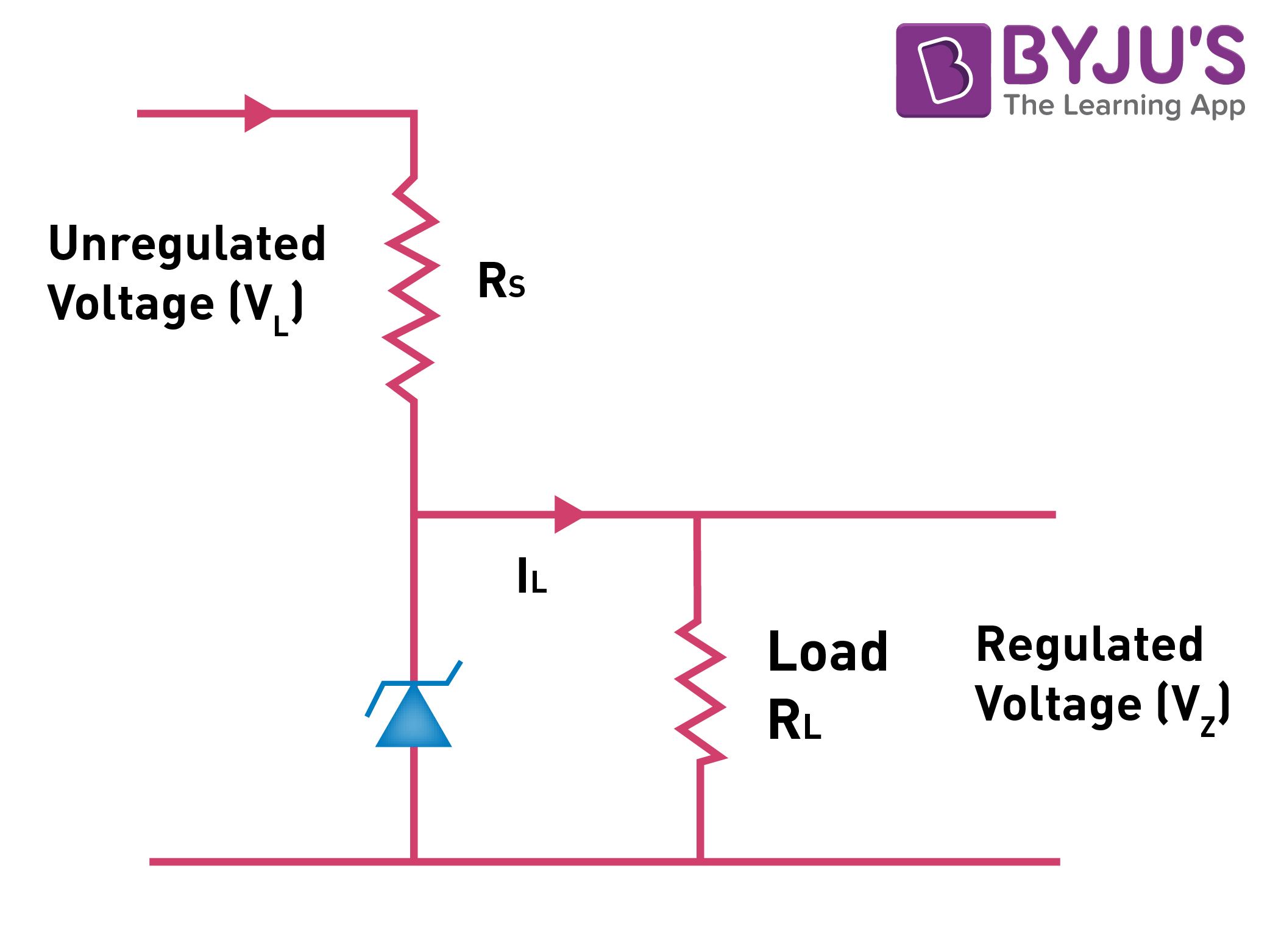
There is a series resistor connected to the circuit in order to limit the current into the diode. It is connected to the positive terminal of the d.c. It works in such a way the reverse-biased can also work in breakdown conditions. We do not use ordinary junction diode because the low power rating diode can get damaged when we apply reverse bias above its breakdown voltage. When the minimum input voltage and the maximum load current is applied, the Zener diode current should always be minimum.
Since the input voltage and the required output voltage is known, it is easier to choose a Zener diode with a voltage approximately equal to the load voltage, i.e. VZ = VL.
Following is the link explaining the difference between Zener breakdown and Avalanche breakdown:
| Difference Between Zener Breakdown and Avalanche Breakdown |
The circuit diagram of a voltage regulator using a Zener diode is shown:

Current through the diode increases when the voltage across the diode tends to increase which results in the voltage drop across the resistor. Similarly, the current through the diode decreases when the voltage across the diode tends to decrease. Here, the voltage drop across the resistor is very less, and the output voltage results normally.
Read more to learn about the Zener diode as a voltage regulator, uses of a Zener diode, and how it is used as a voltage regulator with BYJU’S engaging videos.
Frequently Asked Questions – FAQs
Name the factor which is required for voltage regulation to keep diode in the breakdown region.
Minimum reverse current is required for voltage regulation to keep the diode in the breakdown region.
How to set the breakdown region during manufacturing of the diode?
By controlling the doping level, the breakdown region can be set during the manufacturing of the diode.
What is a Zener breakdown?
When the breakdown occurs in Rectifier as well as the Zener diode, it is known as the Zener breakdown.
What happens to the DC output voltage when the input varies within the limits?
The DC output voltage remains constant when the input varies within the limits as the voltage regulator is used.
State true or false: Voltage regulator is used to vary or regulate the output voltage.
True.


Comments