What Are Dielectrics?
Dielectrics, in general, can be described as materials that are very poor conductors of electric current. They are basically insulators and contain no free electrons. Dielectrics can be easily polarised when an electric field is applied to it, and thus, their behaviour in an electric field is entirely different from that of conductors. You will understand this better in the following sections.
Dielectric Materials
With respect to the atomic view, dielectric materials are classified into two categories.
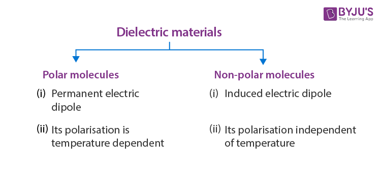
Polar and non-polar molecules help us to understand the dielectric behaviour in an electric field.
Polar Molecules
A polar molecule is one in which the ‘centres of gravity’ of the positive charges (i.e., protons) and negative charges (i.e., electrons) do not coincide. Such molecules are called permanent electric dipoles, as they have permanent dipole moments. Some common polar molecules are HCl, H2O, N2O, NH3, H2S, C2H5OH, and SO2.
In a molecule of HCl, there is an excess positive charge on the H-ion and an equal negative charge on the Cl-ion. The molecule, therefore, has a dipole moment at every instant and is a polar molecule. Another interesting example of polar molecules is H2O.
In the water molecule, two O-H bonds are not placed opposite to each other (unlike the CO2 molecule) but are inclined at an angle of about 105°. The hydrogen ion forms a dipole moment with each of the oxygen ions, and there is a net dipole moment
(i) In the absence of an electric field, the electric dipole moments of these polar molecules point in random directions [Fig. (b)] and cancel each other. Therefore, even though each molecule has a dipole moment, the average moment per unit volume is zero.
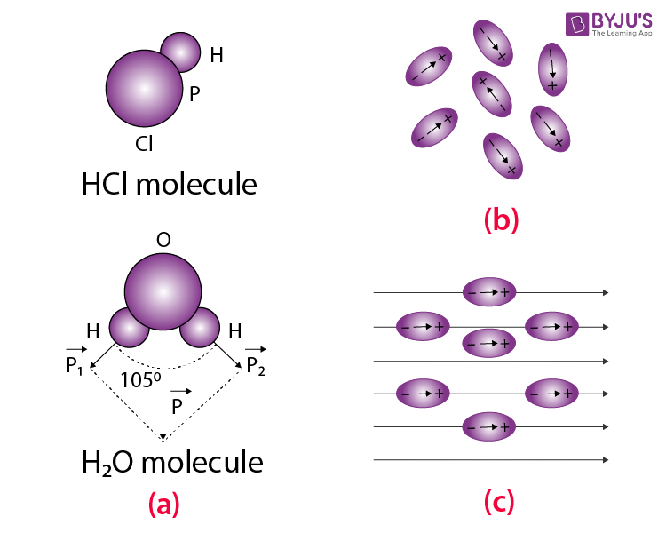
(ii) On the application of an electric field, the dipole moments of these molecules align themselves parallel to the direction of the electric field, as shown in figure (c). But this alignment is incomplete due to the thermal vibrations of the molecules. It is obvious that the alignment of the molecules with the applied field increases if,
- The electric intensity of the field is increased.
- Temperature is decreased.
It should be noted that increased electric intensity may also increase the dipole moment. It is due to the reason that with increased electric intensity, the distance between the centres of gravity of the positive and negative charges increases, which results in an increase in the dipole moment.
Also Read: Dimensional Formula of Dielectric Constant
Non-polar Molecules
A non-polar molecule is one in which the centres of gravity of positive charges (i.e., protons) and negative charges (i.e., electrons) coincide. These molecules, thus, do not have any permanent dipole moment.
Some common examples of non-polar molecules are CO2, CCl4, oxygen (O2), nitrogen (N2), hydrogen (H2), methane (CH4) and ethane (C2H6).
In a molecule of CO2, the oxygen ions are symmetrically placed with respect to the carbon ion. Hence, the dipole moment is zero [Figure (a)].
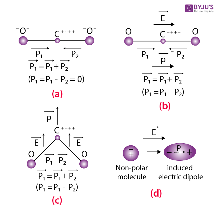
In CCl4, the external electric field changes the orientation of the C-Cl bond and thus produces an induced dipole moment.
Thus, in general, when a non-polar molecule is placed in an electric field, the centres of positive and negative charges get displaced, and the molecule is then said to have been polarised, as shown in figure (d). Such a molecule is then called the induced electric dipole, and its electric dipole moment is called the induced electric dipole moment. As soon as the electric field is removed, the induced electric dipole moment disappears.
The induced electric dipole moment is proportional to the applied electric field but is almost independent of temperature. Further, the induced dipole is parallel to the electric field right at the time of its creation.
The main difference between the polar and the non-polar molecules is the temperature dependence of dipole moment in the case of polar molecules and no such dependence in the case of non-polar molecules.
Dielectric Polarisation
A dielectric may be made up of polar or non-polar molecules. But the net effect of an external field is almost the same, i.e., the external field will compel the molecules to align their dipole moments along its own direction.
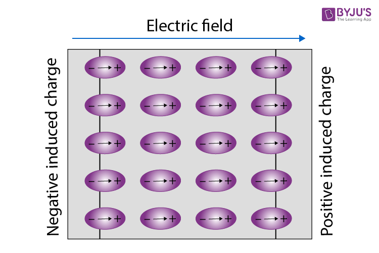
Let us consider a dielectric slab in an electric field which is acting in the direction shown in the figure. The arrangement of charges within the molecules of the dielectric in the electric field is the same as shown in the figure. The positive charges move in the direction of the field, and the negative charges move in the opposite direction. In other words, the electric dipoles align themselves with the direction of the field. In this state, the entire dielectric and its molecules are said to be polarised.
The alignment of the dipole moments of the permanent or induced dipoles with the direction of the applied electric field is called polarisation.
Within the two extremely thin surface layers indicated by shaded regions, there is an excess negative charge in one layer and an excess equal positive charge in the other layer.
The induced charges on the surfaces of the dielectric are due to these layers. These charges are not free, but each is bound to a molecule lying on or near the surface. That is why these charges are called bound charges or fictitious charges. Within the remaining dielectric, the net charge per unit volume remains zero. Thus, although the dielectric is polarised, yet as a whole, it remains electrically neutral.
Obviously, the positive induced surface charge must be equal in magnitude to the negative induced surface charge. Thus, in polarisation, the internal state of the slab is characterised not by an excess charge but by the relative displacement of the charges within it.
Polarisation can thus also be thought of as a phenomenon in which an alignment of positive and negative charges takes place within the dielectric, resulting in no net increase in the charge of the dielectric.
Polarisation is defined as the electric dipole moment per unit volume.
The dimensional formula for P is:
Dipole moment/volume
- I = Current
- L = Length
- T = Time
The polarised slab can be considered as a single dipole consisting of the induced charges –qi and +qi at the opposite faces separated by a distance equal to the thickness of the slab. The dielectric slab fills the entire space between the plates. A small gap left between its surfaces and those of the plates is only for the sake of clarity.
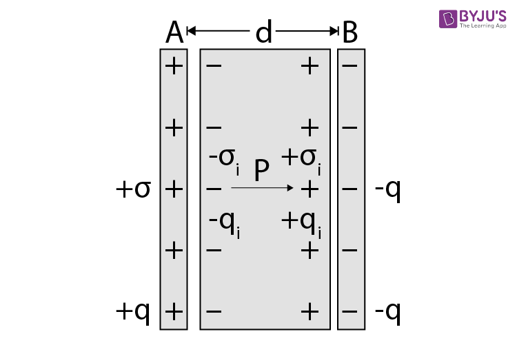
Electric dipole moment of the entire slab
Volume of the entire slab = area × thickness = Ad
Thus, polarisation, P
Where σi = surface density (charge per unit area) of the induced charge.
Obviously,
It is found that in most dielectrics (except certain types of crystals, called ferroelectrics), the polarisation P is directly proportional to the resultant electric field E in the dielectric. That is,
Where
The susceptibility of the vacuum is zero. This is due to the reason that in a vacuum, there are no molecules whose charges can be displaced by an electric field.
Induced Electric Field of Dielectric
Electric Field Inside a Dielectric
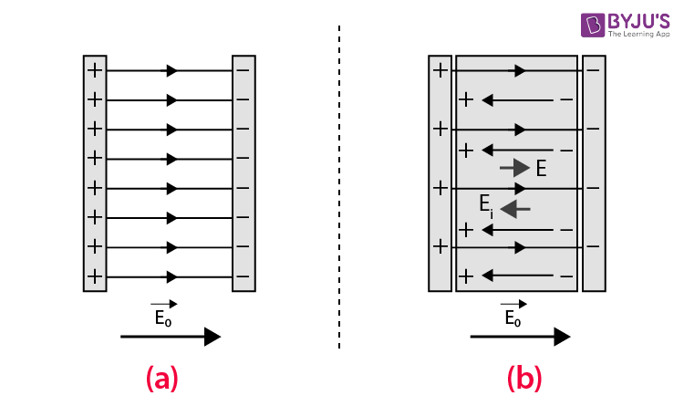
The field in the dielectric is only weakened and never completely cancelled. This is due to the fact that the charges in the dielectric are not free to move beyond a particular distance, and as such, they are not displaced to such an extent that the induced field is equal to the applied field. We find that though a steady current cannot pass through an insulator, an electric field can. That is the reason for calling insulators as dielectrics. Dielectric means transmitting electric effects without conducting.
Dielectrics – Properties and Applications

Related Terms
(a) Induced charge or bound charge
Electric field-induced dielectric is E = E0 – Ei
Or
Or
Since
Or
Or
Thus,
For a conducting slab,
(b) Dielectric Constant (εr)
The resultant electric field (E) inside a dielectric slab inserted in an electric field E0 existing between the plates of a capacitor is given by
E = E0 – Ei
According to Gauss’s theorem,
Electric intensity due to induced surface charges on the dielectric, i.e.,
Or
Or
For vacuum,
Since
The electric field is weakened by introducing a dielectric slab between the plates of a charged parallel-plate capacitor.
If V0 is the potential difference between the plates of the capacitor without dielectric and V with dielectric, then
Or
Since
The potential difference between the plates is reduced by introducing a dielectric between the plates of a charged parallel-plate capacitor.
If C0 and C denote the capacitances of the capacitor without and with dielectric, then
Or
The relative permittivity or dielectric constant of a dielectric is thus defined as the ratio of the capacitance of a capacitor with a dielectric and its capacitance without a dielectric.
Further, since
The capacitance of a capacitor increases if a dielectric is placed between its plates.
(c) Dielectric breakdown
The maximum potential gradient that can exist in a material without its electrical breakdown is called its dielectric strength.
The unit of dielectric strength is the same as that of the electric field, i.e., V/m. If the field strength in the material exceeds the dielectric strength, the insulating properties will break down, and the medium will begin to conduct. A medium with high dielectric strength increases the maximum operating voltage.
Effect of Dielectrics on Capacitors
(a) The capacitance of a parallel plate capacitor with a dielectric slab
Let a dielectric slab of thickness t be introduced between the plates of the capacitor, which are at a distance d apart, as shown in the figure.
Here, E0 is the external (i.e., applied electric field), Ei is the induced electric field in the slab, and E is the resultant electric field inside the slab, i.e., E = E0 – Ei. We know that
If no dielectric is present, the pd is given by
When the dielectric slab is present, the pd is given by
This is because within the space (d – t) not filled by the slab, the field is E0, whereas, within the slab of thickness t, the field is E.
Let C and C0 be the values of the capacitance of the capacitor with and without dielectric, respectively, between its plates.
Clearly,
Or
Further, as
It is obvious that C > C0. Thus, the presence of a dielectric slab between the plates of a capacitor increases its capacitance.
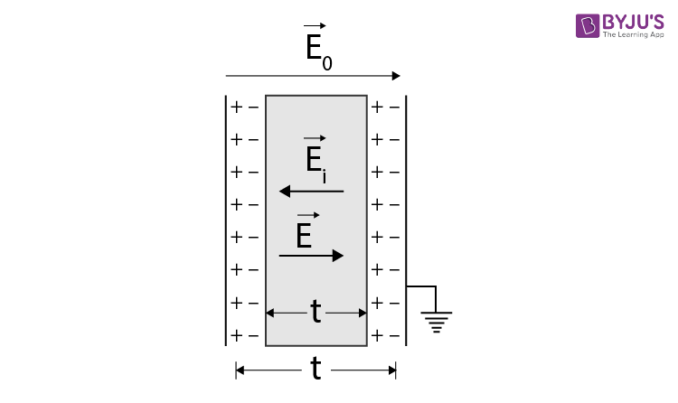
Let a conducting slab of thickness t be introduced between the plates of the capacitor, which are at a distance, d apart [Figure]. Here, E0 is the external (i.e., applied) electric field, and E is the resultant electric field inside the slab.
If no conducting slab is present, the pd is given by
When the conducting slab is present, the pd is given by
Let C and C0 be the values of the capacitance with and without the conducting slab, respectively, between its plates.
Clearly,
Or
It is obvious that C > C0. Thus, the presence of a conducting slab between the plates of a capacitor also increases the capacitance of the capacitor.
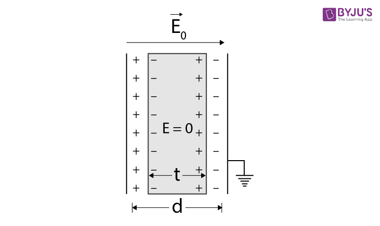
Special cases:
- If t = d (i.e., the space between the capacitor is filled with the conducting slab), C = ∞. In this case, \(\begin{array}{l}{{\in }_{r}}=C/{{C}_{0}}=\infty .\end{array} \)Thus, a conductor is a medium whose dielectric constant is infinity.
- The capacitance of the parallel-plate capacitor increases whether a dielectric slab or a metal plate is inserted in the region between its plates. However, the mechanism involved in the increase of capacitance in the two cases is not the same. In the case of the dielectric slab, polarisation reduces the electric field in the region between the plates, whereas, in the case of a metal plate, the electric field is zero within the region filled by the metal plate.
Frequently Asked Questions on Dielectrics
What are dielectrics?
Dielectrics are insulators. They do not have any free electrons and hence do not conduct electricity. However, they transmit an electric field.
What are the two types of molecules of a dielectric?
Polar molecules and non-polar molecules.
What are polar molecules?
The molecules of a dielectric, which act like tiny electric dipoles and possess a permanent dipole moment, are called polar molecules.
What are non-polar molecules?
The molecules of a dielectric, which do not possess a permanent dipole moment but get induced with a dipole moment in an electric field, are called non-polar molecules.

Comments