Inductors, much like conductors and resistors, are simple components that are used in electronic devices to carry out specific functions. Normally, inductors are coil-like structures that are found in electronic circuits. The coil is an insulated wire that is looped around the central core.
Download Complete Chapter Notes of Electromagnetic Induction
Download Now
Inductors are mostly used to decrease or control the electric spikes by storing energy temporarily in an electromagnetic field, and then releasing it back into the circuit.
What Is an Inductor?
An inductor is a passive component that is used in most power electronic circuits to store energy in the form of magnetic energy when electricity is applied to it. One of the key properties of an inductor is that it impedes or opposes any change in the amount of current flowing through it. Whenever the current across the inductor changes, it either acquires charge or loses the charge in order to equalise the current passing through it. The inductor is also called a choke, a reactor or just a coil.
Also Read: Induction
An inductor is described by its distinctive nature of inductance, which is defined as the ratio of the voltage to the rate of change of current. Inductance is a result of the induced magnetic field on the coil. It is also determined by several factors, such as
- The shape of the coil.
- The number of turns and layers of the wire.
- The space that is given between the turns.
- Permeability of the core material.
- The size of the core.
The SI unit of inductance is henry (H), and when we measure magnetic circuits, it is equivalent to weber/ampere. It is denoted by the symbol L.
Moreover, an inductor is totally different from a capacitor. In the case of a capacitor, it stores energy as electrical energy, but as mentioned above, an inductor stores energy in the form of magnetic energy. One key feature of the inductor is that it also changes its polarity while discharging. In this way, polarity during discharging can be made opposite to the polarity during charging. The polarity of the induced voltage is well explained by Lenz’s law.
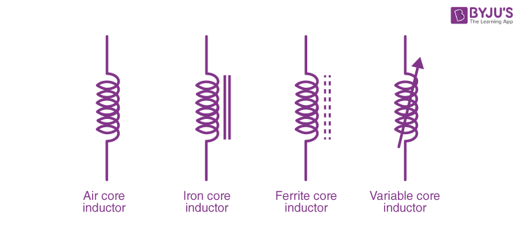
Symbols for an inductor are given below:
Construction of an Inductor
If we look at the construction of an inductor, it usually consists of a coil of conducting material (widely used ones include insulated copper wire) that is wrapped around a core that is made up of plastic material or ferromagnetic material. One advantage of using a ferromagnetic core is that it has high permeability, which helps in increasing the magnetic field and, at the same time, confining it closely to the inductor. Ultimately this results in higher inductance.
On the other hand, inductors with low frequency are usually constructed like transformers. They have cores made up of electrical steel that is laminated to help prevent eddy currents. ‘Soft’ ferrites are also widely used for cores above audio frequencies.
Inductors come in many shapes and types. In some inductors, you will find an adjustable core that allows changing the inductance. Inductors that are used in blocking very high frequencies are mostly made by stringing a ferrite bead on a wire.
Planar inductors are made using a planar core, while small-value inductors are built on integrated circuits using the processes of making interconnects. Typically, an aluminium interconnect is used and fixed in a spiral coil pattern. However, small dimensions have some limitations. They restrict the inductance.
There are also shielded inductors which are commonly used in power regulation systems, lighting, and other systems requiring low-noise operating conditions. These inductors are often partially or fully shielded.
Different Types of Inductors
Depending on the type of material used, inductors can be classified as follows:
- Iron Core Inductor
- Air Core Inductor
- Iron Powder Inductor
- Ferrite Core Inductor, which is divided into:
- Soft Ferrite
- Hard Ferrite
Iron Core Inductor
As the name suggests, the core of this type of inductor is made of iron. These inductors are low-space inductors that have high power and high inductance value. However, they are limited in high-frequency capacity. These inductors are used in audio equipment.
Air Core Inductor
These inductors are used when the amount of inductance required is low. Since there is no core, it does not have a core loss. But the number of turns the inductor must have is more for this type when compared to the inductors with the core. This results in a high-quality factor. Usually, ceramic inductors are often referred to as air-core inductors.
Also Read: Mutual Inductance
Iron Powder Inductor
In this type of inductor, the core is iron oxide. They are formed by very fine and insulating particles of pure iron powder. High magnetic flux can be stored in it due to the air gap. The permeability of the core of this type of inductor is very less and is usually below 100. They are mainly used in switching power supplies.
Ferrite Core Inductor
In this type of inductor, ferrite materials are used as the core. The general composition of ferrites is XFe2O4, where X represents transition material. Ferrites can be classified into two types: soft ferrites and hard ferrites.
- Soft Ferrite: These are materials that have the ability to reverse their polarity without any external energy.
- Hard Ferrite: These are permanent magnets, that is, their polarity will not change even when the magnetic field is removed.
Choke
A choke is a type of inductor that is used mainly for blocking high-frequency alternating current (AC) in an electrical circuit. On the other hand, it will allow DC or low-frequency signals to pass. As the function of this inductor is to restrict the changes in current, it is called a choke. This inductor consists of a coil of insulated wire wound on a magnetic core. The main difference between chokes and other inductors is that they do not require high Q factor construction techniques, which aim to reduce the resistance in inductors found in tuned circuits.
Functions of an Inductor
Inductors can be used for two primary functions:
- To control signals.
- To store energy.
Controlling Signals
Coils in an inductor can be used to store energy. The function of the inductor depends upon the frequency of the current passing through it. That is, higher frequency signals will be passed less easily and vice versa. This function tells that it blocks AC Current and passes DC Current. Hence, it can be used to block AC signals.
Inductors can be used along with capacitors to form LC filters.
Storing Energy
Inductor stores energy in the form of magnetic energy. Coils can store electrical energy in the form of magnetic energy, using the property that an electric current flowing through a coil produces a magnetic field, which in turn, produces an electric current. In other words, coils offer a means of storing energy on the basis of inductivity.
Inductors in Parallel Form
If two terminals of an inductor are connected to two terminals of another inductor, then the inductors are said to be parallel. We know that when resistors are connected in parallel, their effective resistance decreases. Similarly, when inductors are connected in parallel form, their effective inductance decreases. Inductors in parallel are somewhat similar to the capacitors in series.
Consider the example below:
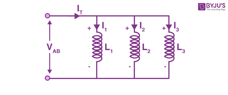
Here, the current flowing through each inductor will be different. This current depends upon the inductance value. However, the voltage across each conductor will be the same. By using Kirchoff’s Current law, the total current is the sum of the current through each branch. That is,
IT = I1 + I2 +I3
We know that the voltage across an inductor is given by the equation
V = L di / dt
We can write,
vAB = LTotal x dlt / dt
VAB = LTotal x d (I1 + I2 + I3) / dt
We can further write it as
vAB = LTotal x dl1 / dt + LTotal x dl2 / dt + LTotal x dl3 / dt
That is,
vAB = LTotal ( V / L1 + V / L2 + V / L3 )
Since voltage are equal, we can simplify the equation as,
1 / LTotal = 1 / L1 + 1 / L2 + 1 / L3
Inductors in Series
When the inductors are chained together in a straight line or when they are connected end to end, then the inductors are said to be in a series connection. We know that when resistors are connected in series, their effective resistance increases.
Similarly, when inductors are connected in series, their effective inductance increases. Inductors in series are somewhat similar to the capacitors in parallel. In order to get the total inductance, it is very easy. You only have to add every inductance. That is, when inductors are connected in series, the total inductance is the sum of all inductance.
Consider the connection below:
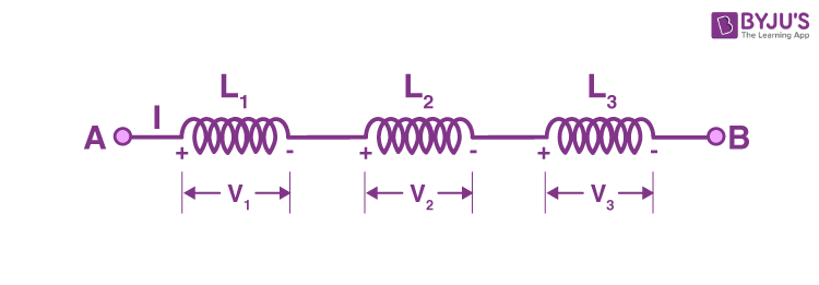
Here, three inductors are connected in series. In this case, the current flowing through each inductor is the same, while the voltage across each inductor is different. This voltage depends upon the inductance value. By using Kirchoff’s voltage law, the total voltage drop is the sum of the voltage drop across each inductor. That is,
VT = V1 + V2 +V3
We know that the voltage across an inductor is given by the equation
V = L di / dt
So, here we can write,
LTotal dl / dt = L1 x dl1 / dt + L2 x dl2 / dt + L3 x dl3 / dt
But
I = I1 = I2 = I3
Therefore,
L dl / dt = L1 x dl / dt + L2 x dl / dt + L3 x dl / dt
LTotal = L1 + L2 + L3
Energy Stored in an Inductor
When a current passes through an inductor, an emf is induced in it. This back emf opposes the flow of current through the inductor. So, in order to establish a current in the inductor, work has to be done against this emf by the voltage source.
Consider a time interval dt.
During this period, work done, dW, is given by
dW = Pdt = – Eidt = iL di / dt x dt = Lidi
To find the total work done, the above expression must be integrated.
W = 0∫ILidi = ½ LI2
Therefore, energy stored in an inductor is given by the equation,
W = ½ LI2
Impedance of an Inductor
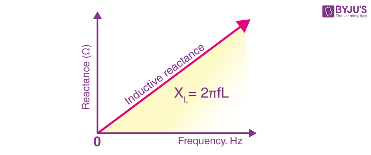
AC resistance mostly determines the opposition of current flowing through a coil. This AC resistance is most commonly known as impedance. In this section, since we are discussing the opposition given by the inductor, this can be called inductive reactance. Inductive reactance, which is given the symbol XL, is the property in an AC circuit that opposes the change in the current.
It is given by the equation,
XL = VL / IL = Lω
From the equation, it is clear that inductive reactance is proportional to frequency.
The plot of frequency vs reactance is given below:
Electromagnetic Induction and Magnetism

Frequently Asked Questions on Inductor
What is the value of the power factor for a pure inductor?
For a pure inductor, the power factor is zero.
What is self-induction?
The phenomenon in which an emf is induced in a coil due to the change of current through the coil itself is known as self-induction.
What is mutual induction?
The phenomenon in which a change of current in one coil induces an emf in another neighbouring coil is called mutual induction.
When is emf induced in a circuit?
An emf is induced in a circuit whenever there is a change in the magnetic flux passing through it.

Comments