| Table of Contents |
What Is a Voltmeter?
A voltmeter, also known as a voltage meter, is an instrument that measures the voltage or potential difference between two points of an electronic or electrical circuit. Usually, the voltmeter is used for Alternating Current (AC) circuits or Direct Current (DC) circuits. Alternatively, Radio Frequency (RF) voltage can also be measured by specialised voltmeters.

A voltmeter measures voltages usually calibrated in volts, millivolts (0.001 volt), or kilovolts (1,000 volts). In order to measure a device’s voltage, a voltmeter is connected in parallel to a device. This setup is important as objects in parallel usually tend to experience the same potential difference. It is connected in parallel with the circuit, mainly because the same voltage drop occurs across it.
A voltmeter also has high internal resistance. This is done mainly because it is used in measuring the potential difference between the two points of the circuit. As such, the current of the measuring device remains the same. In other words, the high resistance of the voltmeter will impede the flow of current through it. This allows the device to take correct readings of the voltage.
Voltmeter Symbol
The voltmeter is usually represented by the letter V, which is placed inside a circle adjoining two terminals.

Types of Voltmeter
Today, a lot of the voltmeters are digital, which gives the readings as numerical displays. However, analogue forms are also available, and this type of voltmeter gives readings wherein a pointer starts moving in some direction, indicating voltage on a scale. Digital voltmeters are preferred because they generally have a higher order of accuracy than analogue voltmeters. We will discuss them in detail below.
Analogue or Analog Voltmeter
An analogue voltmeter is used mainly for measuring the AC voltage. The reading is displayed with the help of a pointer that is fixed on the calibrated scale. The movement of the pointer is affected by the torque that is acting on it. The magnitude of the torque that is developed is directly proportional to the voltage being measured.
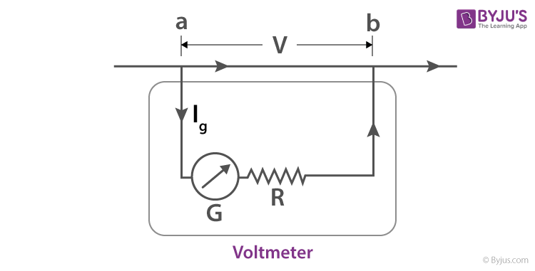
A galvanometer (current meter) that is sensitive and is part of a high resistance series is what makes a basic analogue voltmeter. The meter should have high internal resistance, or else the circuit operation during the test would be interrupted by drawing current significantly. The voltage range displayed by the meter is determined by the series resistance value and the galvanometer sensitivity.
On the other hand, to measure low voltages, an oscilloscope is often used where instantaneous voltage is depicted by the vertical displacement. RF and AC applications have their peak-to-peak and peak voltage measured by the oscilloscopes. Wiring, insulators and heavy-duty probes are crucial for making the meters for measuring high potential differences.
Digital Voltmeter
Another voltmeter that is quite often used among voltage measurement instruments is the digital voltmeter. A digital voltmeter (DVM) measures an unknown input voltage by converting the voltage to a digital value, and then displays the voltage in numeric form. DVMs are usually designed around a special type of analogue-to-digital converter called an integrating converter.
There are different factors that have an impact on the accuracy of the DVM, like input impedance, temperature, and power supply voltage variations of the DVM. Around 10 MΩ is the input resistance of DVMs that are the least expensive. The input resistances for precision DVMs of 1 GΩ or higher for ranges of low voltages (below 20 V). The DVM must be periodically calibrated with a voltage standard, like the Weston Cell, as a way to ensure the manufacturer’s specified tolerances.
Other Types of Voltmeter
These are voltmeters based on their construction.
- MI Voltmeter: Moving Iron (MI) voltmeter is a device that is used for measuring both AC and DC voltages. In this device, the deflection is directly proportional to the voltage of the coil. It is further divided into two types – Attraction Type Moving Iron Instruments and Repulsion Type Moving Iron Instruments.
- Rectifier Voltmeter: These are widely used in AC circuits for measuring voltage. This voltmeter converts the AC into DC with the help of a rectifier. The converted DC signal is then measured using the PMMC instrument.
- PMMC Voltmeter: A Permanent Magnet Moving Coil (PMMC) voltmeter, also known as a D’Arsonval meter or simply galvanometer, measures the current in a coil by observing the coil’s angular deflection in a uniform magnetic field. The current is induced in the PMMC instrument due to the measure and voltage, and deflection of the pointer occurs. The PMMC voltmeter is used for DC measurement.
- Electro-dynamometer Voltmeter: This voltmeter is used to measure the voltage of both AC and DC circuits. The calibration is usually kept the same for both the AC and DC measurement.
- Amplified Voltmeter: These are voltmeters whose sensitivity and input resistance can be increased or decreased. This can be done if the current required to deflect the meter pointer is supplied by an amplifier and power supply.
As described above, voltmeters are made in different styles. Moreover, some portable ones are separately powered with the help of a battery, whereas others are powered by the measured voltage source. In any case, these are usually designed to measure current or resistance and are often used as standard test instruments in electrical work environments.
|
Related Links |
Frequently Asked Questions on Voltmeter
What is a voltmeter?
A voltmeter is a device that measures voltages of direct current or alternating current on a scale, commonly in volts, millivolts, or kilovolts. Most voltmeters are digital that give readings as numerical displays.
How is a voltmeter connected to a circuit?
The voltmeter is always connected in parallel across the circuit.
What is the working principle of a voltmeter?
The basic principle of a voltmeter is that it must be connected in parallel to the circuit in which the voltage has to be measured. A parallel connection is used because a voltmeter is built in such a way that it has a very high resistance value.

Put your understanding of this concept to test by answering a few MCQs. Click ‘Start Quiz’ to begin!
Select the correct answer and click on the “Finish” button
Check your score and answers at the end of the quiz
Visit BYJU’S for all Physics related queries and study materials
Your result is as below
Comments