NCERT Exemplar Solutions Class 10 Science Chapter 12 – Free PDF Download
NCERT Exemplar Solutions for Class 10 Science Chapter 12 Electricity are the study materials necessary for you to understand the questions that can be asked from the Class 10 Science Electricity chapter. It is crucial for students to get acquainted with this chapter in order to score excellent marks in their CBSE Class 10 examination. This solution provides answers to the questions provided in NCERT Class 10 Exemplar book. This page has answers to 18 MCQs, 11 short answer questions and 7 long answer questions.
To help students grasp all the concepts clearly and in-depth, we are offering free NCERT Exemplar for Class 10 Science Chapter 12 here. These exemplars will enable students to learn the correct answers to all the questions given at the end of the chapter. These NCERT Exemplars are prepared by experts and can be used by students as an effective learning tool to improve their conceptual understanding.
Take a closer look at Class 10 Science Chapter 12 NCERT Exemplar below.
Download the PDF of NCERT Exemplar for Class 10 Science Chapter 12 – Electricity


Access Answers to NCERT Exemplar Class 10 Science Chapter 12 – Electricity
Multiple Choice Questions
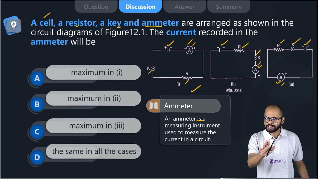
1. A cell, a resistor, a key and ammeter are arranged as shown in the circuit diagrams of Figure12.1. The current recorded in the ammeter will be

(a) maximum in (i)
(b) maximum in (ii)
(c) maximum in (iii)
(d) the same in all the cases
Soln:
The answer is (d) the same in all the cases
Explanation:
There are no changes in any of the circuits, hence current will be same in all the circuits.
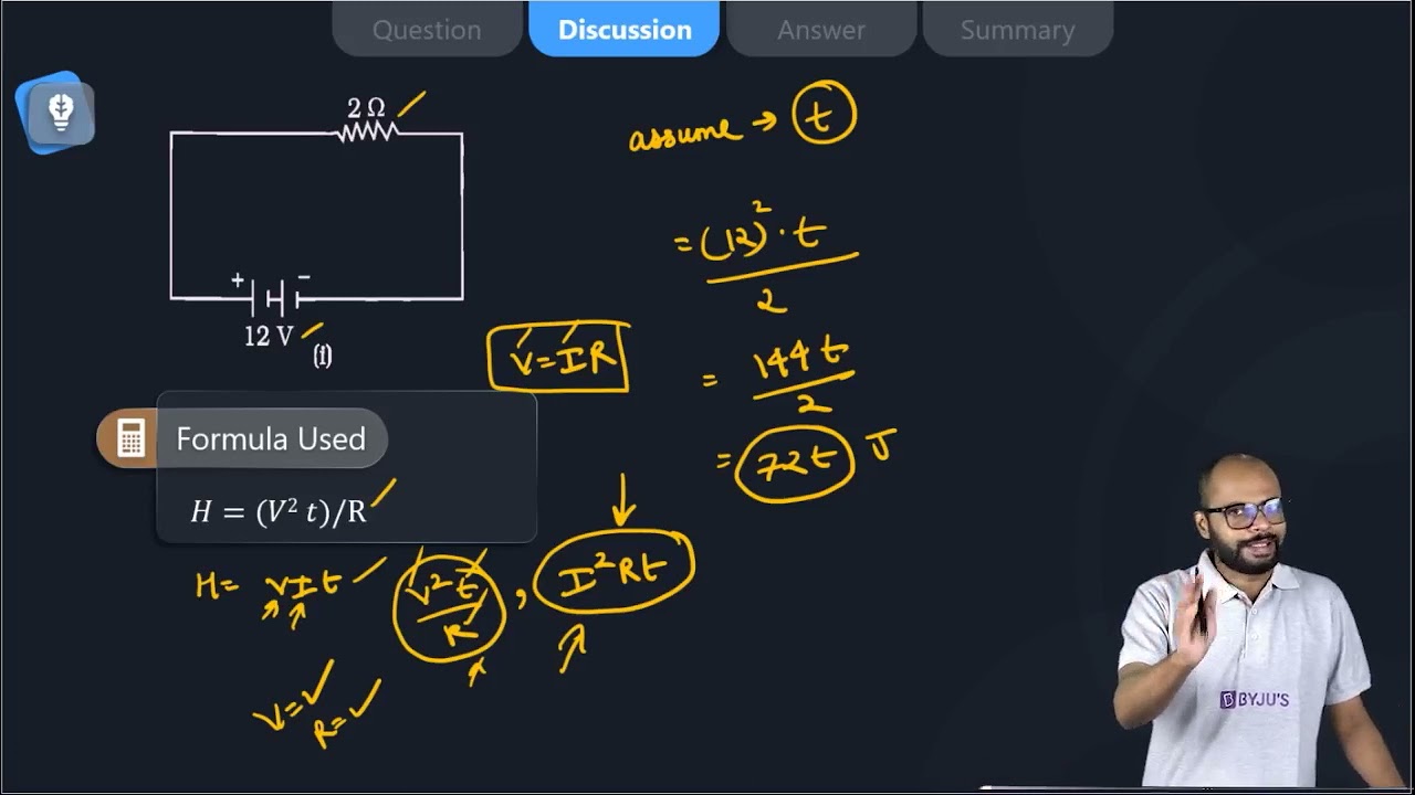
2. In the following circuits (Figure 12.2), the heat produced in the resistor or combination of resistors connected to a 12 V battery will be

(a) same in all the cases
(b) minimum in case (i)
(c) maximum in case(ii)
(d) maximum in case(iii)
Soln:
The answer is (c) maximum in case(ii)
Explanation
Here two transistors are in series. In figure (iii) total resistance will be less than individual resistances as they are connected parallel. Higher resistance produces more heat hence option c) is the right answer.
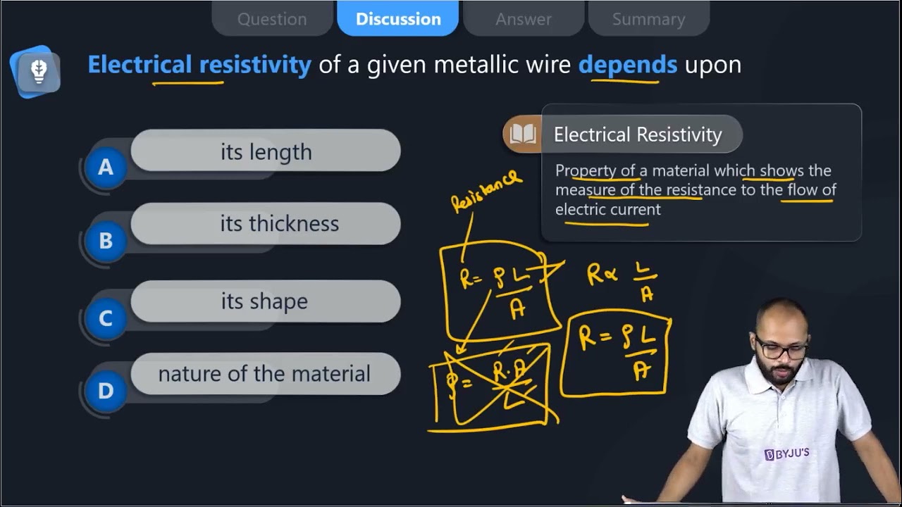
3. Electrical resistivity of a given metallic wire depends upon
(a) its length
(b) its thickness
(c) its shape
(d) nature of the material
Soln:
The answer is (d) nature of the material
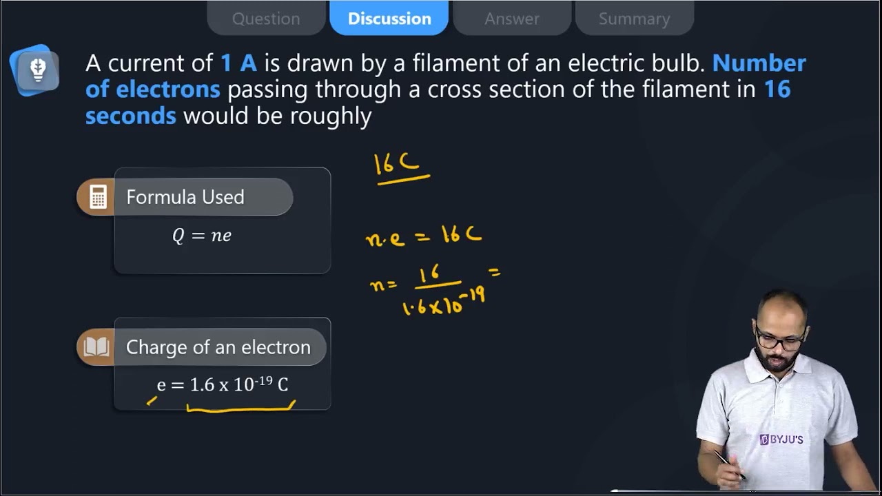
4. A current of 1 A is drawn by a filament of an electric bulb. Number of electrons passing through a cross-section of the filament in 16 seconds would be roughly
(a) 1020
(b) 1016
(c) 1018
(d) 1023
Soln:
Answer is (a) 1020
Explanation:
I = Q/t
Q= It
Q= 1 x 16
Q= 16 q
Q=ne
n = Q/e
n = 16 /1.6 x 10-19
n = 10 x 1019
n = 1020 electrons
The number of electrons flowing is 1020 electrons
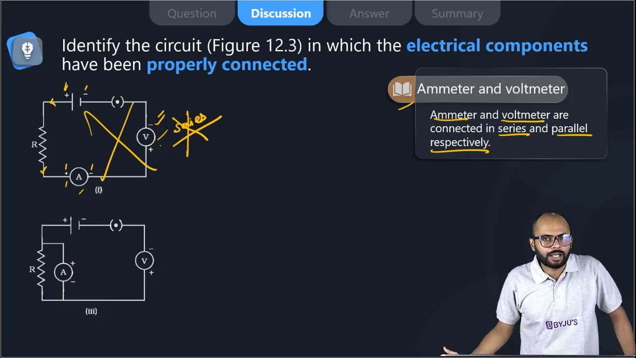
5. Identify the circuit (Figure 12.3) in which the electrical components have been properly connected.

(a) (i)
(b) (ii)
(c) (iii)
(d) (iv)
Soln:
The answer is (b) (ii)
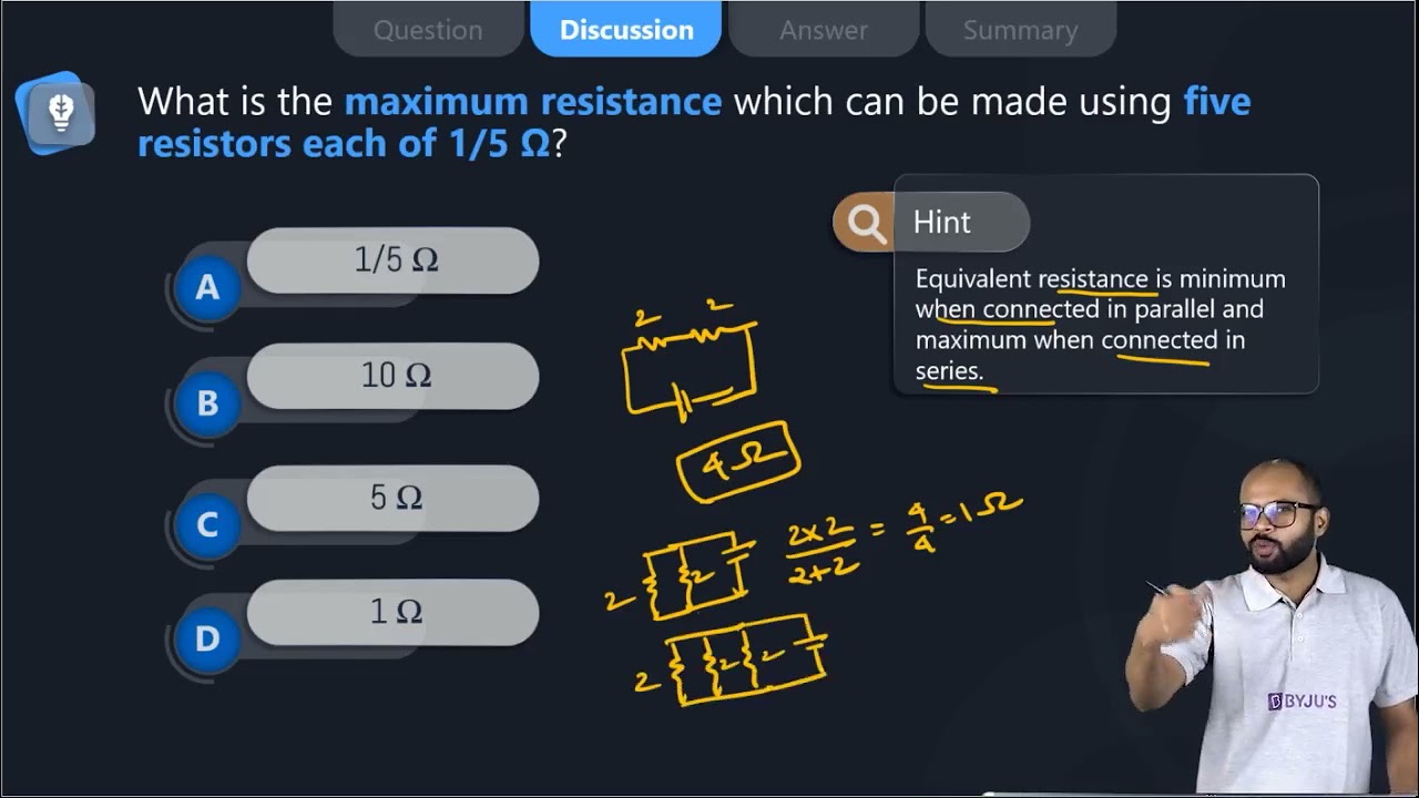
6. What is the maximum resistance which can be made using five resistors each of 1/5 Ω?
(a) 1/5 Ω
(b) 10 Ω
(c) 5 Ω
(d) 1 Ω
Soln:
The answer is (d) 1 Ω
Explanation:
Maximum resistance is obtained when resistors are connected in series.
R=
= 5/5
= 1Ω
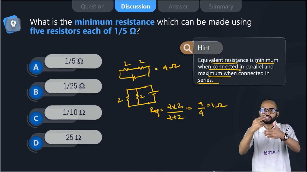
7. What is the minimum resistance which can be made using five resistors each of 1/5 Ω?
(a) 1/5 Ω
(b) 1/25 Ω
(c) 1/10 Ω
(d) 25 Ω
Soln:
Answer is (b) 1/25 Ω
Explanation:
Minimum resistance is obtained when resistors are connected parallel
1/R = 5 + 5 + 5 +5 +5= 25 Ω
R=1/25Ω
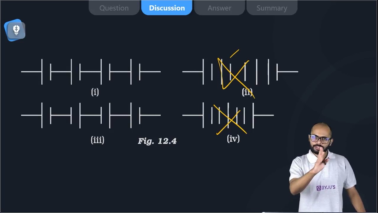
8. The proper representation of the series combination of cells (Figure 12.4) obtaining maximum potential is

(a) (i)
(b) (ii)
(c) (iii)
(d) (iv)
Soln:
The answer is (a) (i)
Explanation:
Here positive terminal of the next cell is adjacent to the negative terminal of the previous cell.
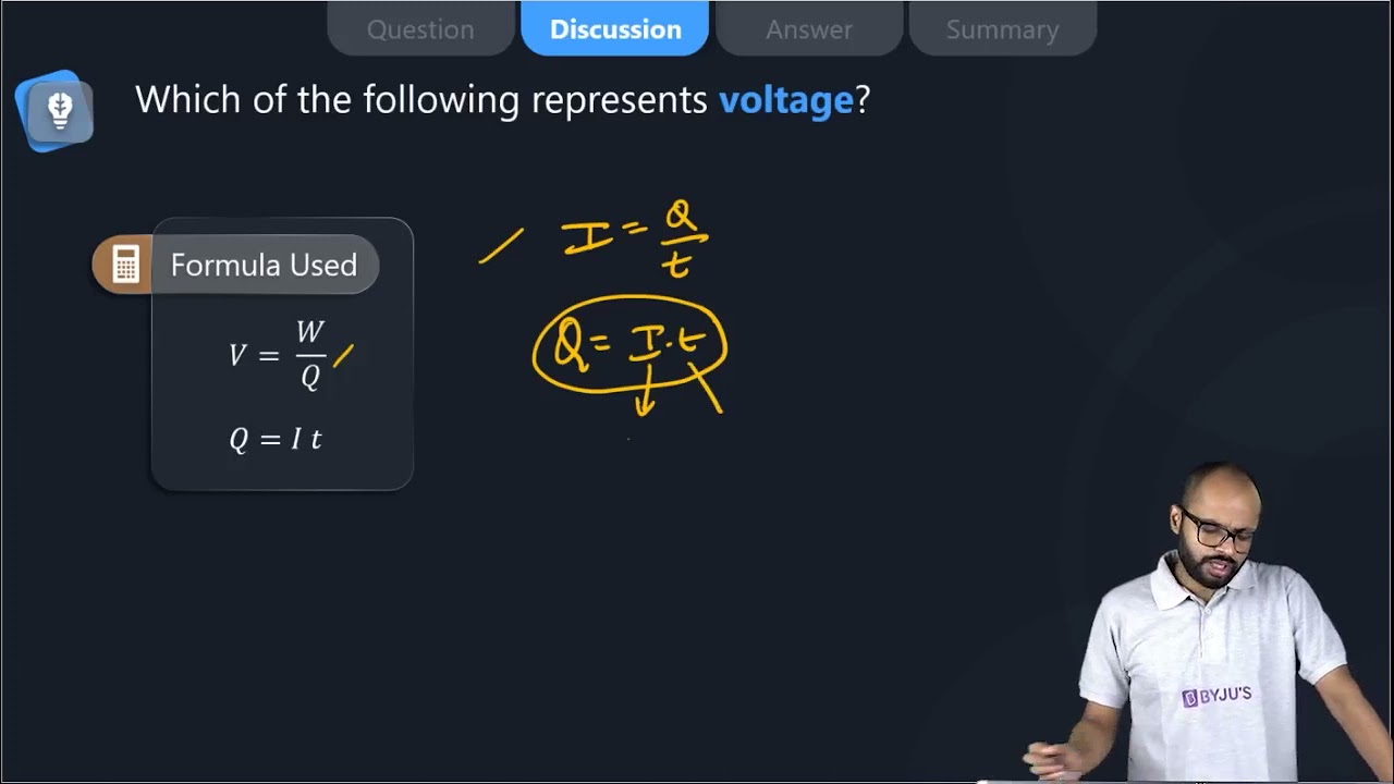
9. Which of the following represents voltage?
(a)
(b) Work done × Charge
(c)
(d) Work done × Charge × Time
Soln:
Answer is
(a)
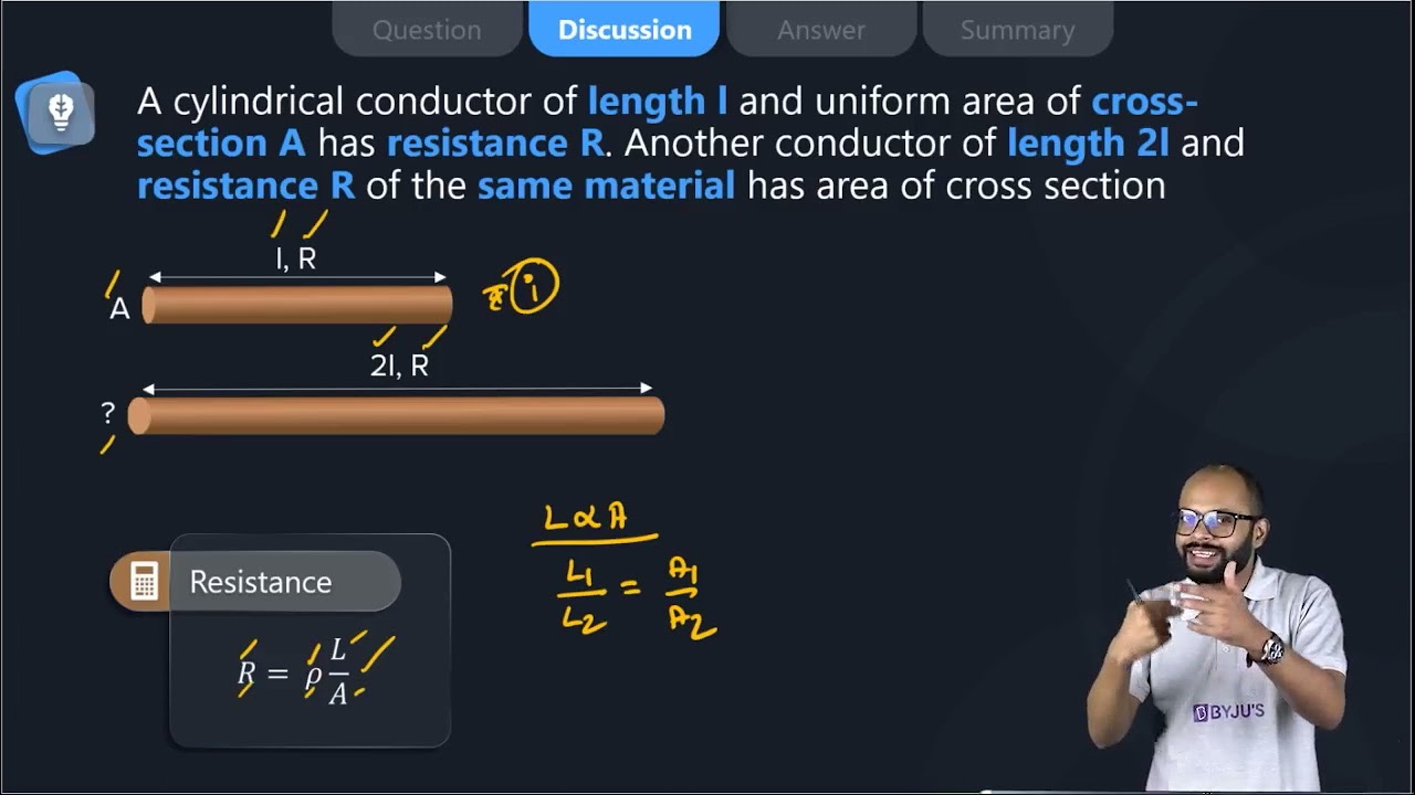
10. A cylindrical conductor of length l and uniform area of crosssection A has resistance R. Another conductor of length 2l and resistance R of the same material has an area of cross-section
(a) A/2
(b) 3A/2
(c) 2A
(d) 3A
Soln:
Answer is (c) 2A
Explanation:
P=
When Length doubles
P=
A=2A
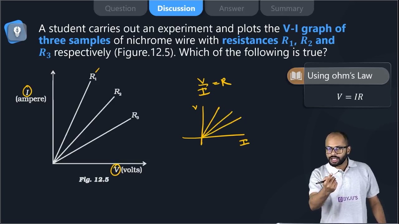
11. A student carries out an experiment and plots the V-I graph of three samples of nichrome wire with resistances R1, R2 and R3 respectively (Figure.12.5). Which of the following is true?

(a) R1 = R2 = R3
(b) R1 > R2 > R3
(c) R3 > R2 > R1
(d) R2 > R3 > R1
Soln:
The answer is (c) R3 > R2 > R1
Explanation:
Current flow is inversely proportional to resistance. Highest resistance will show less flow of current hence answer is c).
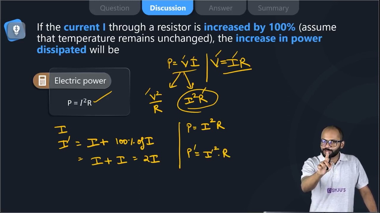
12. If the current I through a resistor is increased by 100% (assume that temperature remains unchanged), the increase in power dissipated will be
(a) 100 %
(b) 200 %
(c) 300 %
(d) 400 %
Soln:
Answer is (c) 300 %
Explanation:
Heat generated by a resistor is directly proportional to the square of the current. Hence, when the current becomes double, dissipation of heat will multiply by 2 =4. This means there will be an increase of 300%.
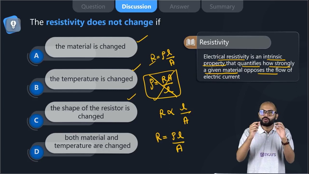
13. The resistivity does not change if
(a) the material is changed
(b) the temperature is changed
(c) the shape of the resistor is changed
(d) both material and temperature are changed
Soln:
Answer is (c) the shape of the resistor is changed
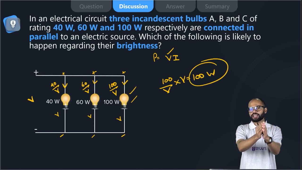
14. In an electrical circuit, three incandescent bulbs A, B and C of rating 40 W, 60 W and 100 W respectively are connected in parallel to an electric source. Which of the following is likely to happen regarding their brightness?
(a) The brightness of all the bulbs will be the same
(b) The brightness of bulb A will be the maximum
(c) The brightness of bulb B will be more than that of A
(d) The brightness of bulb C will be less than that of B
Soln:
Answer is (c) Brightness of bulb B will be more than that of A
Explanation:
Bulbs are connected in parallel so the resistance of combination would be less than the arithmetic sum of the resistance of all the bulbs. So. there will be no negative effect on the flow of current. As a result, bulbs would glow according to their wattage.
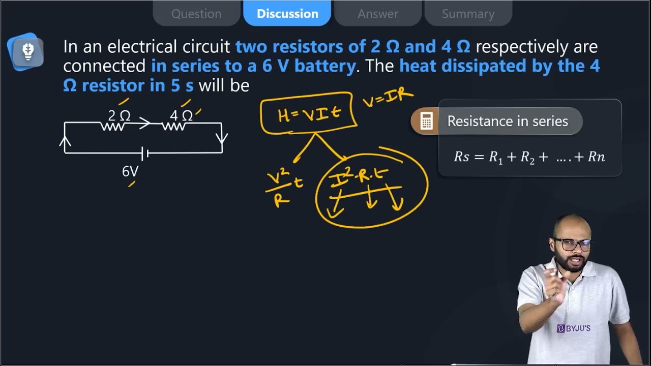
15. In an electrical circuit, two resistors of 2 Ω and 4 Ω respectively are connected in series to a 6 V battery. The heat dissipated by the 4 Ω resistor in 5 s will be
(a) 5 J
(b) 10 J
(c) 20 J
(d) 30 J
Soln:
Answer is (c) 20 J
Explanation:
Equivalent resistance of the circuit is R = 4+2 = 6Ω
current, I= V/R = 6/6= 1A
the heat dissipated by 4-ohm resistor is, H = I2Rt = 20J
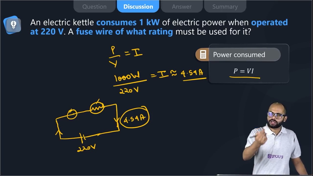
16. An electric kettle consumes 1 kW of electric power when operated at 220 V. A fuse wire of what rating must be used for it?
(a) 1 A
(b) 2 A
(c) 4 A
(d) 5 A
Soln:
The answer is (d) 5 A
Explanation:
P=V x I
Or 1000 w = 220v x I
I =
= 5 A
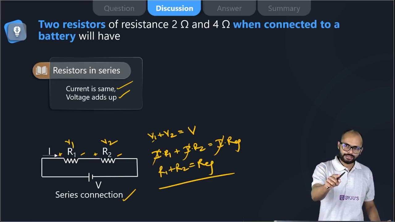
17. Two resistors of resistance 2 Ω and 4 Ω when connected to a battery will have
(a) same current flowing through them when connected in parallel
(b) same current flowing through them when connected in series
(c) the same potential difference across them when connected in series
(d) different p
Soln:
The answer is (b) same current flowing through them when connected in series
Explanation:
In series combination current does not get divided into branches because resistor receives a common current.
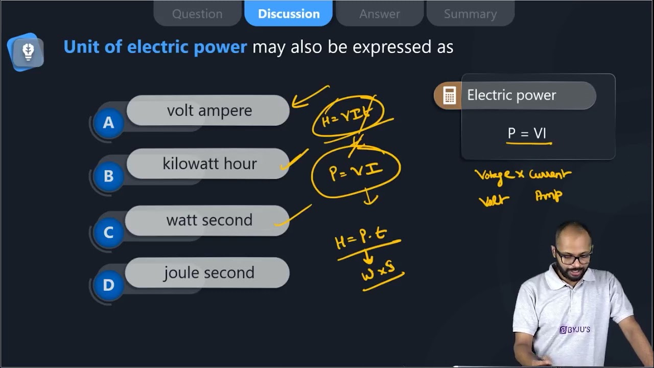
18. Unit of electric power may also be expressed as
(a) volt-ampere
(b) kilowatt-hour
(c) watt-second
(d) joule second
Soln:
The answer is (a) volt-ampere
Explanation:
Volt-ampere (VA) is the unit used for the apparent power in an electrical circuit. A watt-second (also watt-second, symbol W s or W. s) is a derived unit of energy equivalent to the joule. The joule-second is the unit used for Planck’s constant.
Short Answer Questions
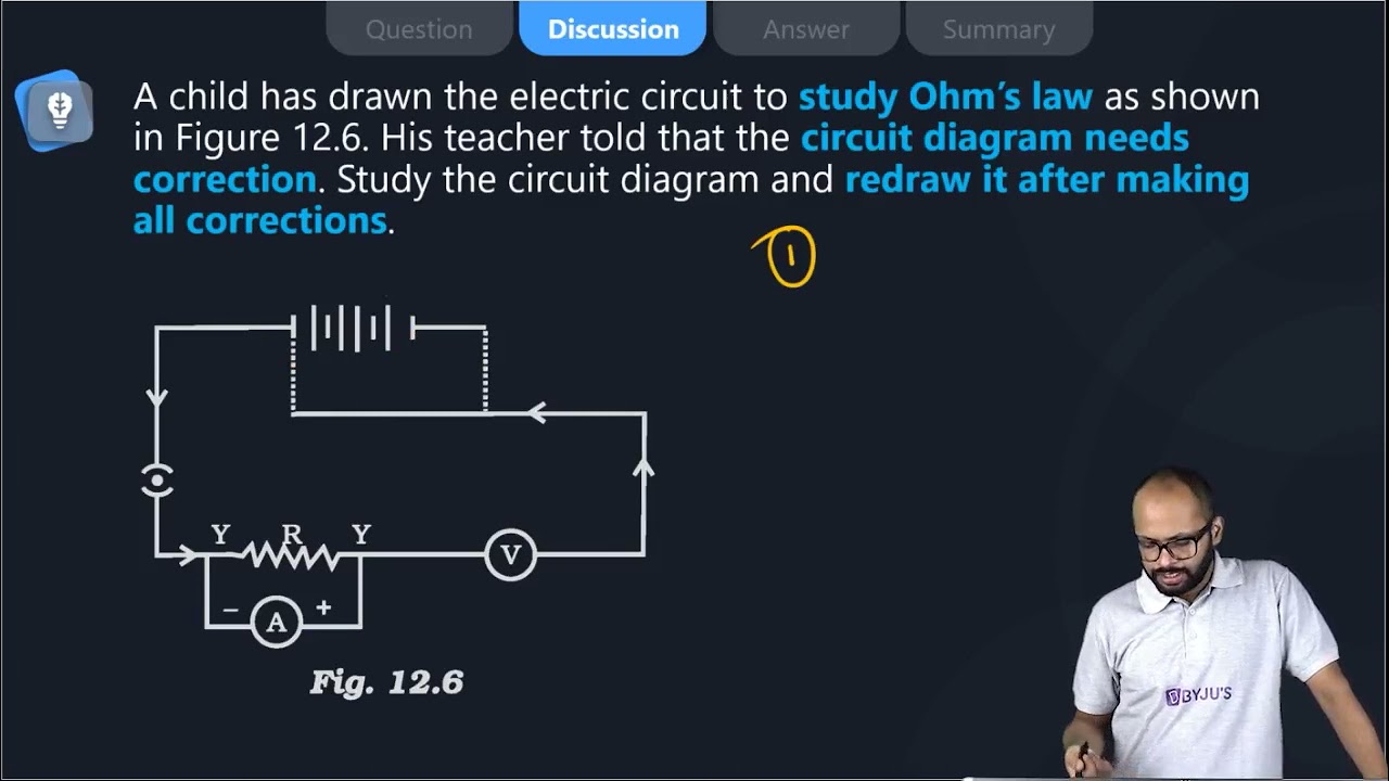
19. A child has drawn the electric circuit to study Ohm’s law as shown in Figure 12.6. His teacher told that the circuit diagram needs correction. Study the circuit diagram and redraw it after making all corrections.

Soln:

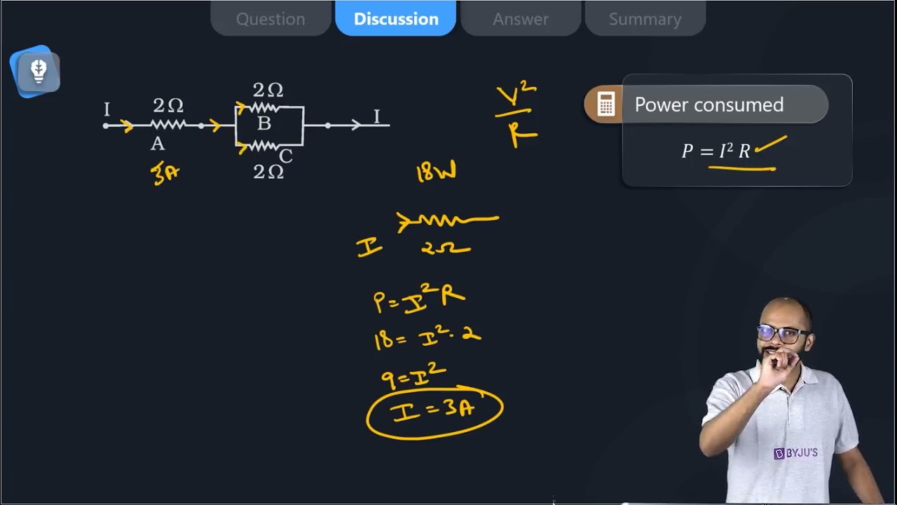
20. Three 2 Ω resistors, A, B and C, are connected as shown in Figure 12.7. Each of them dissipates energy and can withstand a maximum power of 18W without melting. Find the maximum current that can flow through the three resistors?

Soln:
Current P= I2R
18W = I2 x 2Ω
I2 = 18W/ 2Ω
= 9
I= 3A
Maximum value of current passing through A is 3A.
Current through B = Current through C = 1/2 x Current through A
Current through B = Current through C = 1/2 x 3
Current through B = Current through C = 1.5 A
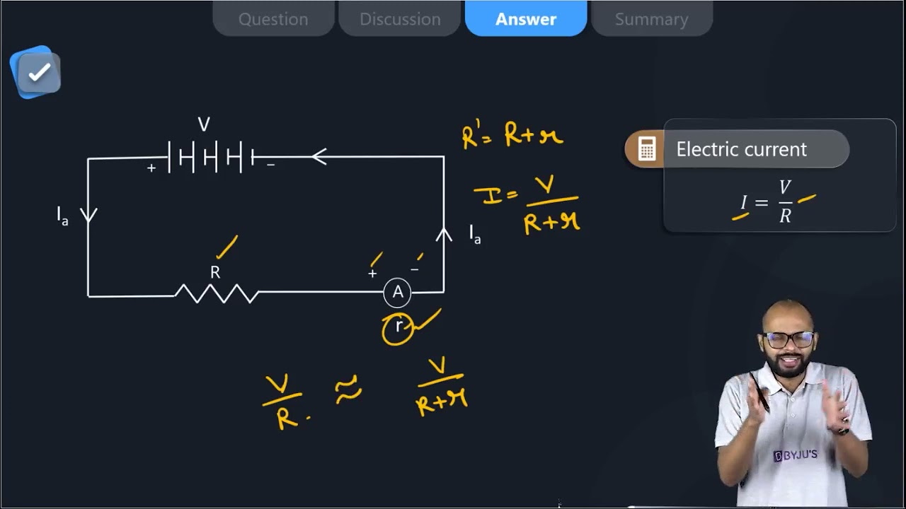
21. Should the resistance of an ammeter be low or high? Give reason.
Soln:
Resistance of ammeter should be zero because ammeter should not affect the flow of current.
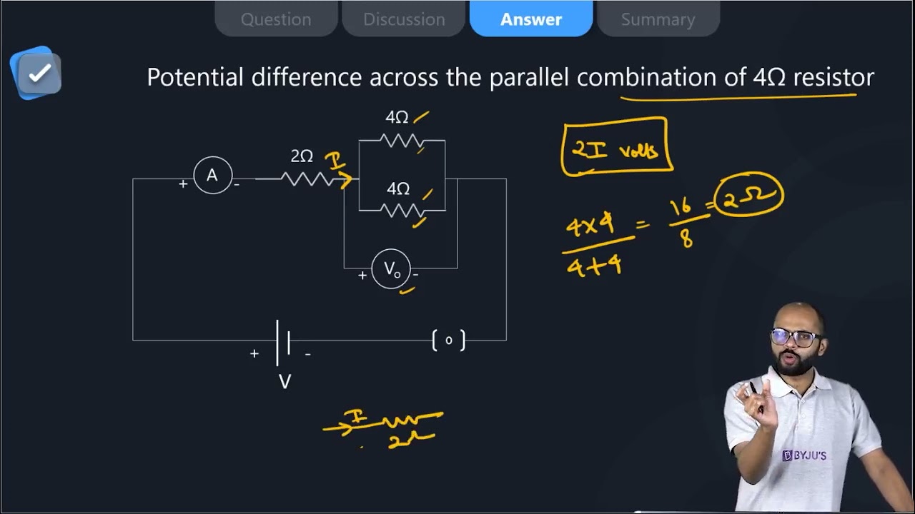
22. Draw a circuit diagram of an electric circuit containing a cell, a key, an ammeter, a resistor of 2 Ω in series with a combination of two resistors (4 Ω each) in parallel and a voltmeter across the parallel combination. Will the potential difference across the 2 Ω resistor be the same as that across the parallel combination of 4Ω resistors? Give reason.
Soln:

Total resistance for parallel combination of 40 resistors can be calculated as follows:
R= 2 Ω
Thus, resistance of parallel combination is equal to resistance of resistors in series. So, potential difference across 20 resistance will be same as potential difference across the other two resistors which are connected in parallel.
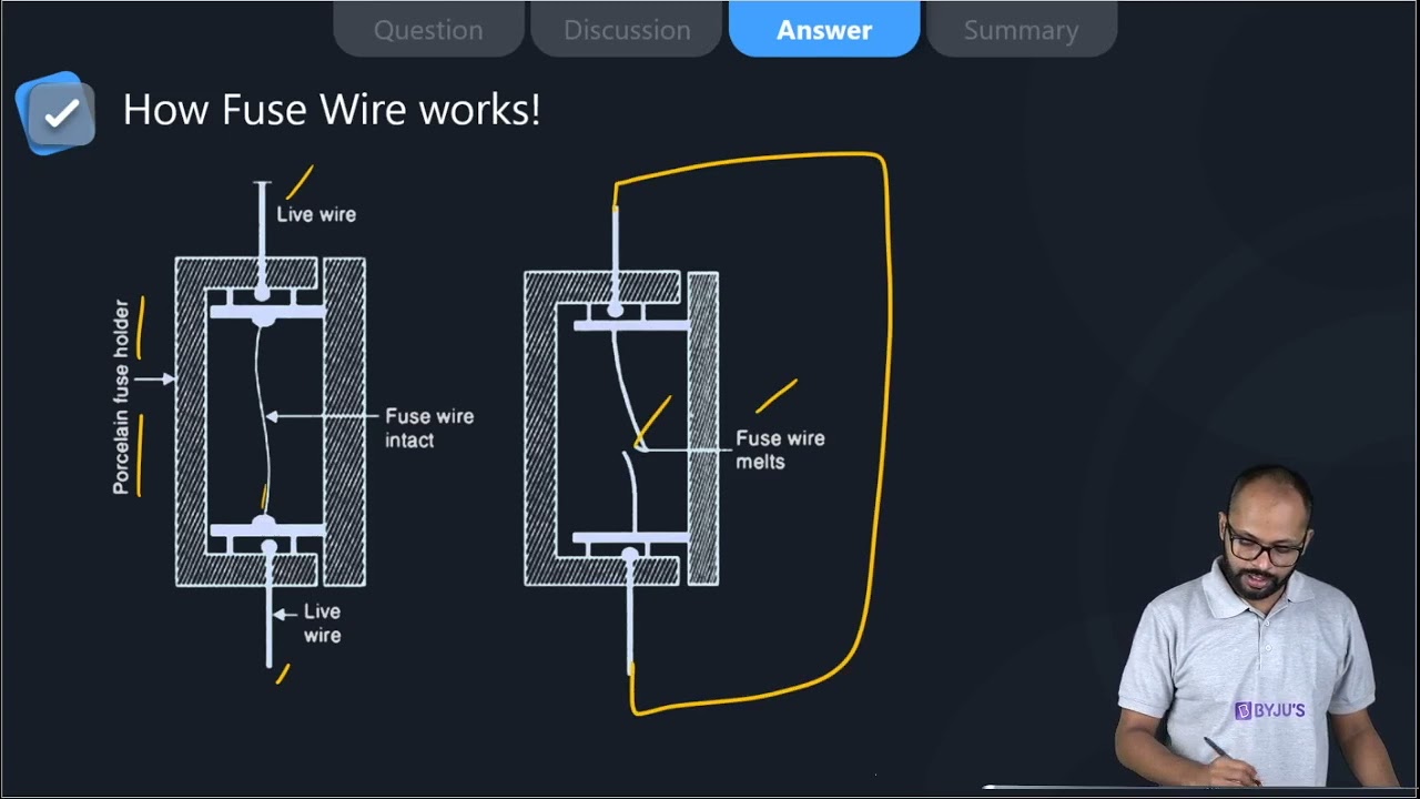
23. How does use of a fuse wire protect electrical appliances?
Soln:
Fuse wire has great resistance than the main wiring. When there is significant increase in the electric current. Fuse wire melts to break the circuit. This prevents damage of electrical appliance.
24. What is electrical resistivity? In a series electrical circuit comprising a resistor made up of a metallic wire, the ammeter reads 5 A. The reading of the ammeter decreases to half when the length of the wire is doubled. Why?
Soln:
Property of the conductor which resists the flow of electric current is called resistivity. Resistance for a particular material is unique. Resistance is directly proportional to length of conductor and inversely proportional to current flow.
When length is doubled resistance becomes double and current flow reduces to half. This is the reason for the decrease in ammeter reading.
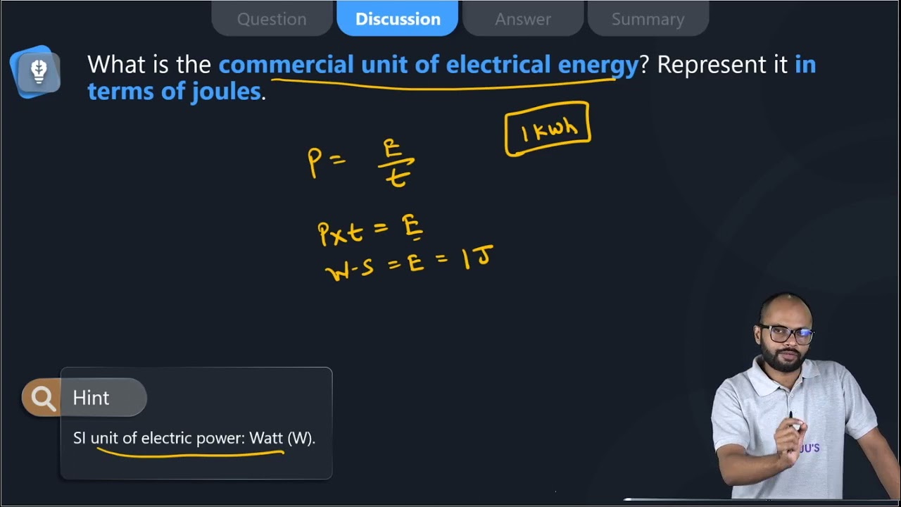
25. What is the commercial unit of electrical energy? Represent it in terms of joules.
Soln:
Commercial unit of electrical energy is kilowatt/hr
1 kw/hr = 1 kW h
= 1000 W × 60 × 60s
= 3.6 × 10⁶ J
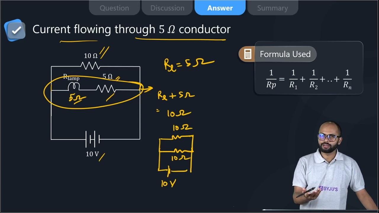
26. A current of 1 ampere flows in a series circuit containing an electric lamp and a conductor of 5 Ω when connected to a 10 V battery. Calculate the resistance of the electric lamp. Now if a resistance of 10 Ω is connected in parallel with this series combination, what change (if any) in current flowing through 5 Ω conductor and potential difference across the lamp will take place? Give reason.
Soln:
1) Let R be the resistance of the electric lamp. In series total resistance = 5 + R
I = v/r
1 = 10/5+R
R = 5 ohm
2) V across Lamp + conductor = 10 V
V acoess Lamp = I × R = 1 * 5 = 5 Volt
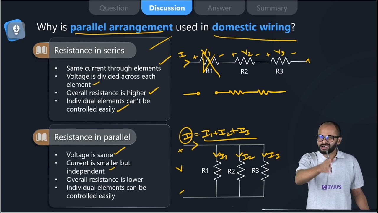
27. Why is parallel arrangement used in domestic wiring?
Soln:
Parallel arrangement used in domestic wiring because it provides the same potential difference across each electrical appliance.
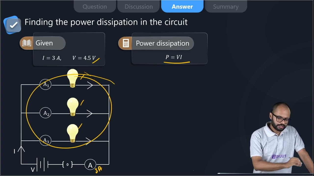
28. B1 , B2 and B3 are three identical bulbs connected as shown in Figure 12.8. When all the three bulbs glow, a current of 3A is recorded by the ammeter A.
- What happens to the glow of the other two bulbs when the bulb B1 gets fused?
- What happens to the reading of A1 , A2 , A3 and A when the bulb B2 gets fused?
- How much power is dissipated in the circuit when all the three bulbs glow together?
Soln:
i) Potential difference does not get divided in parallel circuit. Hence glowing of other bulbs will not get affected when bulb one is fused.
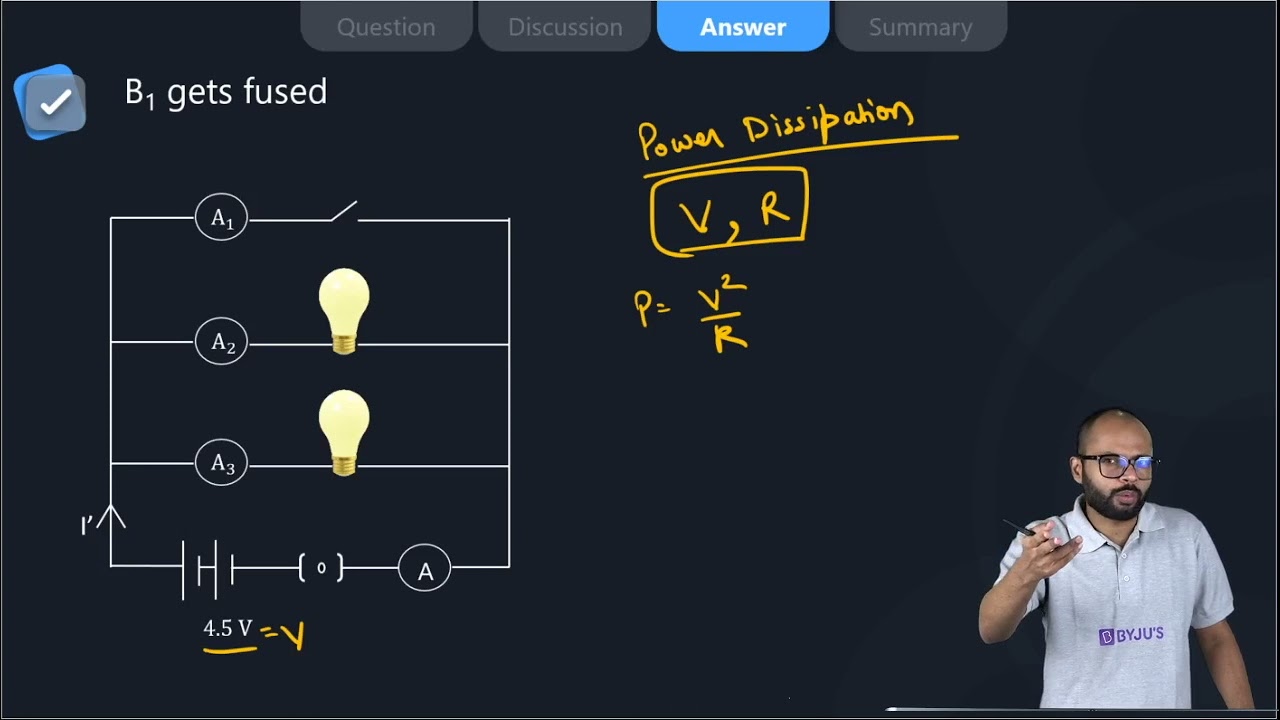
ii) Ammeter A shows a reading of 3A. This means each of the Al. A2, and A3 show IA reading.
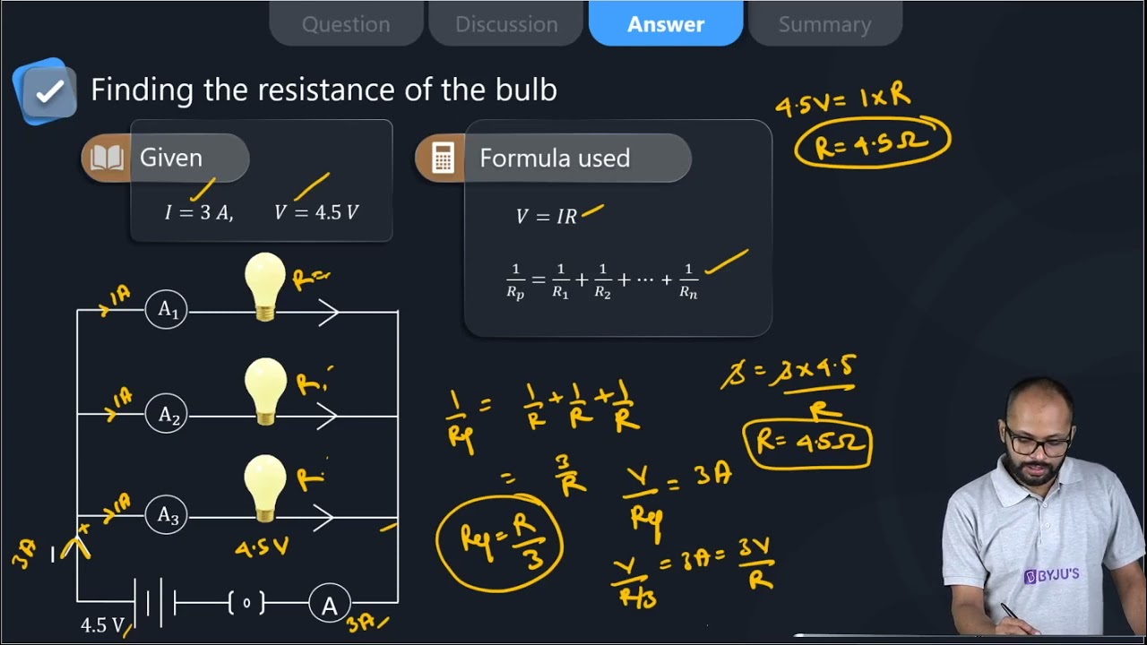
iii) R= V/I = 4.5V/3A= 1.5Ω
Now P= I2R
= (3A)2 x 1.5 Ω
= 13.5 W
Long Answer Questions
29. Three incandescent bulbs of 100 W each are connected in series in an electric circuit. In another circuit another set of three bulbs of the same wattage are connected in parallel to the same source.
(a) Will the bulb in the two circuits glow with the same brightness? Justify your answer.
(b) Now let one bulb in both the circuits get fused. Will the rest of the bulbs continue to glow in each circuit? Give reason.
Soln:
(Resistance of the bulbs in series will be three times the resistance of single bulb. Hence, the current in the series combination will be one-third compared to current in each bulb in parallel combination. The parallel combination bulbs will glow more brightly.
The bulbs in series combination will stop glowing as the circuit is broken and current is zero. However the bulbs in parallel combination shall continue to glow with the same brightness.
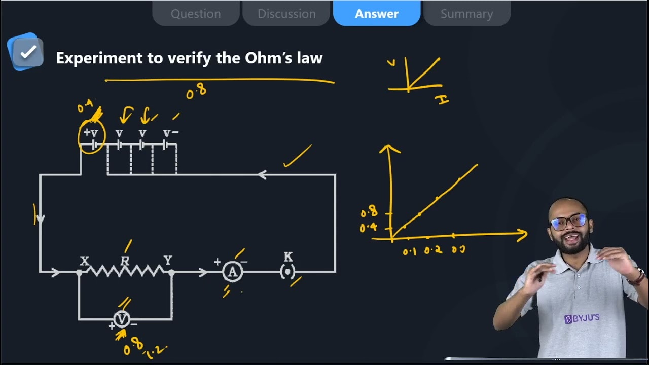
30. State Ohm’s law? How can it be verified experimentally? Does it hold good under all conditions? Comment.
Soln:
Ohm’s law states that at constant temperature potential difference (voltage) across an ideal conductor is proportional to the current through it.
V/I = R

Verification of Ohm’s law
Set up a circuit as shown in Fig. consisting of a nichrome wire XY of length, say 0.5 m, an ammeter, a voltmeter and four cells of 1.5 V each. (Nichrome is an alloy of nickel, chromium, manganese, and iron metals.)
First use only one cell as the source in the circuit. Note the reading in the ammeter I, for the current and reading of the voltmeter V for the potential difference across the nichrome wire XY in the circuit. Tabulate them in the Table given
Next, connect two cells in the circuit and note the respective readings of the ammeter and voltmeter for the values of current through the nichrome wire and potential difference across the nichrome wire.
Repeat the above steps using three cells and then four cells in the circuit separately.

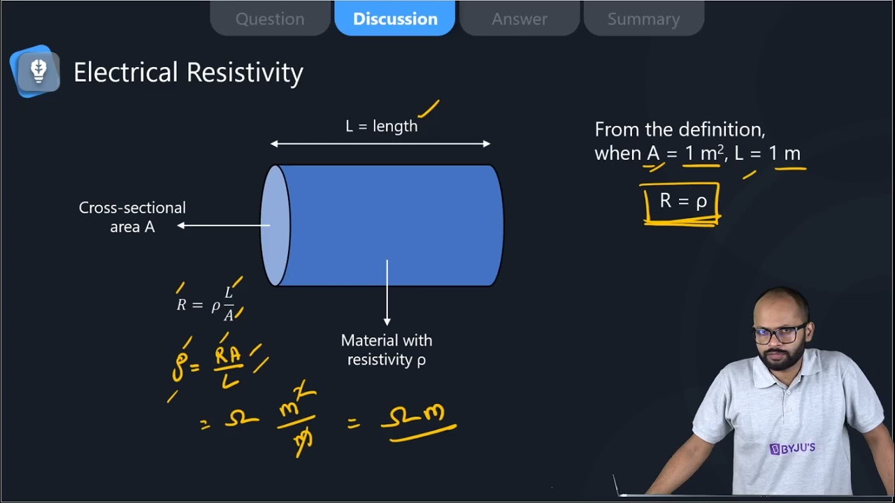
31. What is electrical resistivity of a material? What is its unit? Describe an experiment to study the factors on which the resistance of conducting wire depends.
Soln:
Resistivity is an inherent property of a conductor which resists the flow of electric current. Resistivity of each material is unique. SI unit of resistance is Ωm.
Experiment to study the factors on which the resistance of conducting wire depends.
Take a nichrome wire, a torch bulb, a 10 W bulb and an ammeter (0 – 5 A range), a plug key and some connecting wires.
Set up the circuit by connecting four dry cells of 1.5 V each in series with the ammeter leaving a gap XY in the circuit, as shown in Fig. 12.4.
Observation:
It is observed that resistance depend on material of conductor
Length of conductor determines resistance
Resistance depends on area of cross-section.

Complete the circuit by connecting the nichrome wire in the gap XY. Plug the key. Note down the ammeter reading. Take out the key from the plug. [Note: Always take out the key from the plug after measuring the current through the circuit.]
Replace the nichrome wire with the torch bulb in the circuit and find the current through it by measuring the reading of the ammeter.
Now repeat the above step with the 10 W bulb in the gap XY. Are the ammeter readings different for different components connected in the gap XY? What do the above observations indicate?
You may repeat this Activity by keeping any material component in the gap. Observe the ammeter readings in each case. Analyse the observations.
32. How will you infer with the help of an experiment that the same current flows through every part of the circuit containing three resistances in series connected to a battery?
Soln:
- Collect three resistors R1, R2, R3 in series to make the circuit.
- Use ammeter to see the changes observed in the current flow.
- Remove R1 and take the reading of potential difference of R2 and R3
- Remove R2 and take the reading of potential difference of R1 and R3

Observation:
Ammeter reading was the same in each case so it can be inferred that the current remains the same in the circuit. To cross-check one can place ammeter and different places and observe the current flow.
33. How will you conclude that the same potential difference (voltage) exists across three resistors connected in a parallel arrangement to a battery?
Soln:
Take three resistors R1, R2 and R3, connect them in parallel to make a circuit; as shown in the figure.
Use voltmeter to take reading of potential difference of three resistors in parallel combination.
Now, remove the resistor R1 and take the reacting of the potential difference of remaining resistors combination.
Then, remove the resistor R2, and take the reading of potential difference of remaining resistor.

Observation:
In each case Voltmeter reading was the same which shows that the same potential difference exists across three resistors connected in a parallel arrangement.
34. What is Joule’s heating effect? How can it be demonstrated experimentally? List its four applications in daily life.
Soln:
According to Joules heating effect heat produces in a resistor is
- Directly proportional to square of current for the given resistor.
- Directly proportional to resistance for a given current,
- Directly proportional to the time of current flowing through the resistor.
This can be expressed as
H = I2Rt
H is heating effect, I is electric current, R is resistance and t is time.
Experiment to demonstrate Joules law of heating
- Take a water heating immersion rod and connect to a socket which is connected to the regulator. It Is important to recall that a regulator controls the amount of current flowing through a device.
- Keep the pointer of regulator on the minimum and count the time taken by immersion rod to heat a certain amount of water.
- Increase the pointer of the regulator to the next level. Count the time taken by immersion rod to heat the same amount of water.
- Repeat above step for higher levels on regulator to count the time.
Observation:
It is seen that with an increased amount of electric current, less time is required o heat the same amount of water. This shows Joule’s Law of Heating.
Application:
Electric toaster, oven, electric kettle and electric heater etc. work on the basis of leafing effect of current.
35. Find out the following in the electric circuit given in Figure 12.9
(a) Effective resistance of two 8 Ω resistors in the combination
(b) Current flowing through 4 Ω resistor
(c) Potential difference across 4 Ω resistance
(d) Power dissipated in 4 Ω resistor (e) Difference in ammeter readings, if any
Soln:

| Also Access |
| NCERT Solutions for Class 10 Science Chapter 12 |
| CBSE Notes for Class 10 Science Chapter 12 |
NCERT Exemplar Class 10 Chapter 12 Electricity
Sometimes we might have wondered about what constitutes electricity or how does it flow in an electric circuit, or what controls and regulates the current through an electric circuit? In Chapter 12 Electricity, students will find answers to these questions. They will also learn about other topics like the heating effect of electric current and its applications, the circuit diagram, Ohm’s law, resistors and conductors, electrical potential and potential difference.
Topics covered in Class 10 NCERT Exemplar Solutions for Science Chapter 12 Electricity
- Introduction
- Current
- The potential difference – Definition of volt and voltmeter
- Ohm’s law – Ohm and resistance
- Factors on which the resistance of the conductor depends – Resistivity
- Resistors in series – Total/resultant/overall and voltage across each resistor
- Resistors in parallel
- The advantage of parallel combination over the series combination
- Heating effect of an electric circuit – Joule’s law of the heating effect of electric current, electric fuse and electric power.
With BYJU’S, students can excel in their studies and can score better marks in the board examination. Class 10 is an important stage of a student’s life, as it consists of topics which are necessary to understand thoroughly for future entrance exams. To help you grasp the concepts clearly, BYJU’S brings you notes, sample papers, and animation videos. For a customised learning experience, visit BYJU’S website or download BYJU’S – The Learning App.
Frequently Asked Questions on NCERT Exemplar Solutions for Class 10 Science Chapter 12
List out the topics included in Chapter 12 of NCERT Exemplar Solutions for Class 10 Science.
Introduction
Current
The potential difference – Definition of volt and voltmeter
Ohm’s law – Ohm and resistance
Factors on which the resistance of the conductor depends – Resistivity
Resistors in series – Total/resultant/overall and voltage across each resistor
Resistors in parallel
The advantage of parallel combination over the series combination
Heating effect of an electric circuit – Joule’s law of the heating effect of electric current, electric fuse and electric power
How can we demonstrate Joule’s heating effect according to Chapter 12 of NCERT Exemplar Solutions for Class 10 Science?
1. Take a water heating immersion rod and connect it to a socket in the regulator. It is important to recall that a regulator controls the amount of current flowing through a device.
2. Keep the pointer of the regulator on the minimum and count the time taken by the immersion rod to heat a certain amount of water.
3. Increase the pointer of the regulator to the next level. Count the time taken by the immersion rod to heat the same amount of water.
4. Repeat the above step for higher levels on the regulator to count the time.
Are NCERT Exemplar Solutions for Class 10 Science Chapter 12 the best study materials for students?
Also, Read
Comments